POP_UP_MESSAGE_CONTENT


What is ACLR?

ACLR generally uses dBc format, so it is sufficient to subtract the main channel power (dBm) from the adjacent channel power (dBm).

The impact of ACLR
The definition of ACLR is very simple and clear, but what impact will ACLR have on the system if its metrics are not good?
The most direct impact is that there is a very large unknown signal on the adjacent channel of the main channel. If the nearby communication system happens to be working on the adjacent channel, this unknown signal will cause great interference to the communication system. This huge interference will have a significant impact on the communication system, and even make it unable to work.
On the other hand, according to the law of conservation of power, if there is a relatively large leakage power on adjacent channels, the power of the main channel will decrease, and the efficiency of the communication system will be relatively low, resulting in a significant power consumption problem.
System requirements for ACLR
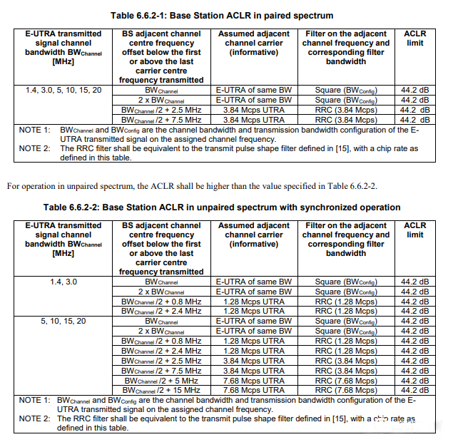
So, for all wireless communication systems, there are strict ACLR requirements, especially in base stations. For example, for LTE fourth generation communication systems, there are clear requirements for ACLR of LTE transmitters in 3GPP TS 36.141 version 9.12.0 Release 9: ACLR>44.2dBc.
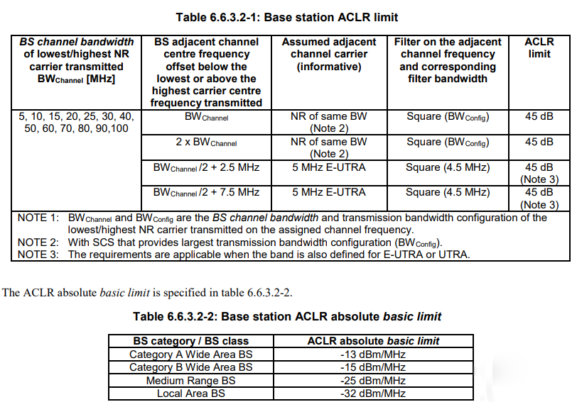
In 5G NR, there are higher requirements for ACLR, and in general, the ACLR of the base station should be greater than 45dB. Please refer to the requirements for ACLR in 3GPP TS 38.104 version 15.2.0 Release 15 for details.
Correspondingly, at the UE end, the transmission power should be lower, so the requirements for ACLR are generally lower. For example, in 3GPP TS 38.101-1 version 15.2.0 Release 15, the specifications for ACLR at the UE end are given.
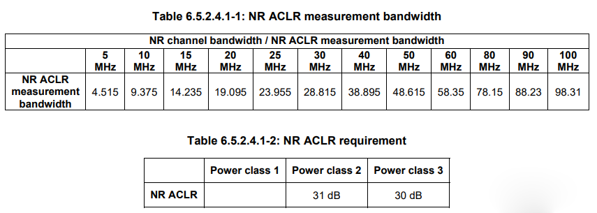
So, for the requirements of ACLR, different wireless systems have different definitions. When designing, students must design RF systems that meet the requirements according to the corresponding wireless communication standards.
How to improve the ACLR of the system?
There are many factors that can lead to the deterioration of ACLR, but the most significant one is the nonlinearity of PA. Because the leakage of adjacent channel power is itself caused by the nonlinearity of the system.
As shown in the figure below, we divide a carrier signal into several subcarriers. Due to the nonlinear effect, every two subcarriers will generate an intermodulation signal on the left and right sides of the carrier, which causes power filling in adjacent channels. In a TA by ADI, the relationship between ACLR and IMD is presented. If the power of the subcarrier and IMD are known, the value of ACLR can be calculated.
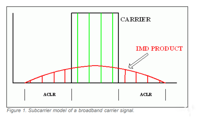
If the output power of the power amplifier is too high, close to the compression point, the power of IIP3 and IIP5 products generated in adjacent channels will also be too high. And these high-power IMD products happen to fall in adjacent channels, which can lead to high ACLR. This is the reason for the occurrence of poor ACLR at maximum power.
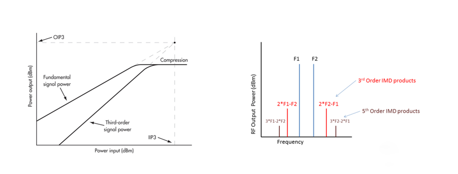
In this case, in order to improve ACLR, the primary task is to improve the linearity of PA. At this point, the output power of PA can be reduced to operate in the linear region, or DPD can be used to improve the linearity of PA at high power; Alternatively, choose a PA with higher linearity.
The second point can be achieved by improving the losses of PA backend devices, such as filters and antennas. The loss here includes both return loss and insertion loss.
From the perspective that reducing the output power of PA can improve ACLR, the low insertion loss of the post filter antenna can ensure that PA can meet the power requirements of the system even at low output power; On the other hand, the good matching of PA output ports not only ensures maximum signal power transmission, but also minimizes the impact of reflected power on the system, especially on DPD. This can be achieved through good cascade matching in the later stage, as well as the selection of low loss components and PCBs.
The third point is to ensure clean PA input. The nonlinearity of active devices can cause intermodulation distortion, both at the PA end and in the front Tx. If there is significant intermodulation distortion in the previous Tx link, its impact on the system will increase after PA amplification. In this case, a channel filter can be added to the PA front-end to filter out the intermodulation distortion generated by the front-end, thereby improving the ACLR performance of this RF transmission link.


