POP_UP_MESSAGE_CONTENT


Tutorial on Frequency Control and Timing Application of Quartz Crystal Resonators and Oscillators (Part 4)
Allan Deviation
Also called two - sample deviation ,or square-root of the " Allan variance ," it is the standard method of describing the short term stability of oscillators in the time domain. It is denoted by σy(τ ),
where

The fractional frequencies,
 are measured over a time
interval, τ; (yk+1 - yk) are the differences between pairs of
successive measurements of y, and, ideally, < > denotes a time average of an infinite number of (y k+1 - y k)2 . A good estimate can be obtained by a limited number, m, of measurements
(m≥100). σy(τ ) generally denotes ·
 , i.e.,

Why σy(τ)?
Classical variance:

diverges for some commonly observed noise
processes, such as random walk, i.e., the variance increases with increasing number of data points.
l Allan variance:
• Converges for all noise processes observed in precision oscillators.
• Has straightforward relationship to power law spectral density types.
• Is easy to compute.
• Is faster and more accurate in estimating noise processes than the Fast Fourier Transform.
Frequency Noise and σy(τ )
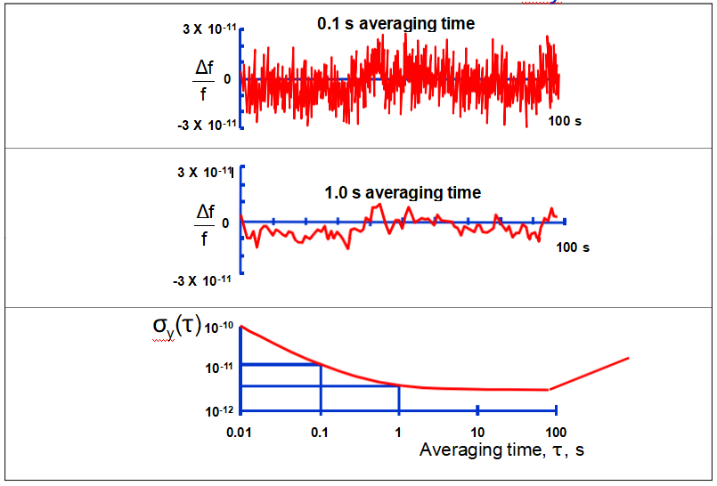
Time Domain Stability
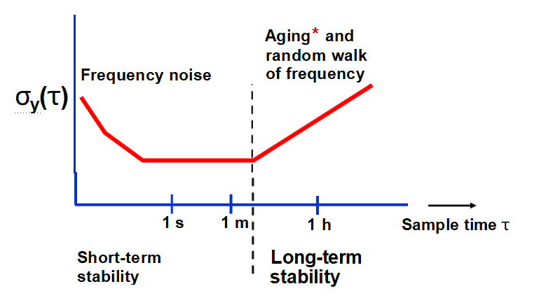
*For σy(τ ) to be a proper measure of random frequency fluctuations, aging must be properly subtracted from the data at long τ’s.
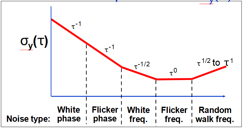
Below the flicker of frequency noise (i.e., the “flicker floor”) region, crystal oscillators typically show τ-1 (white phase noise) dependence. Atomic
standards show τ-1/2 (white frequency noise) dependence down to about the
servo-loop time constant, and τ-1 dependence at less than that time constant.
Typical τ’s at the start of flicker floors are: 1s for a crystal oscillator, 103s for a
Rb standard and 105s for a Cs standard. At large τ’s, random walk of frequency and aging dominate.
Pictures of Noise
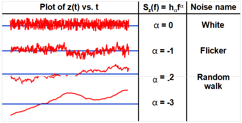
Plots show fluctuations of a quantity z(t), which can be,e.g., the output of a counter (Δf vs. t) or of a phase detector (φ[t] vs. t). The plots show simulated time-domain behaviors
corresponding to the most common (power-law) spectral densities; h α is an amplitude
coefficient. Note: since S Δf = f 2S φ , e.g. white frequency noise and random walk of phase are equivalent.
Spectral Densities

In the frequency domain, due to the phase deviation, φ(t), some of
the power is at frequencies other than ν0 . The stabilities are
characterized by "spectral densities." The spectral density, SV(f), the
mean-square voltage <V2(t)> in a unit bandwidth centered at f, is not a good measure of frequency stability because both ε (t) and φ(t) contribute to it, and because it is not uniquely related to frequency fluctuations
(although ε (t) is often negligible in precision frequency sources.)
The spectral densities of phase and fractional-frequency fluctuations, Sφ(f) and Sy(f), respectively, are used to measure the stabilities in the
frequency domain. The spectral density Sg(f) of a quantity g(t) is the mean square value of g(t) in a unit bandwidth centered at f. Moreover,
the RMS value of g2 in bandwidth BW is given by

Mixer Functions
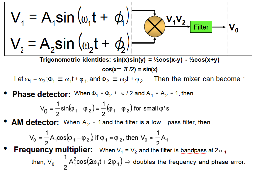
Phase Detector
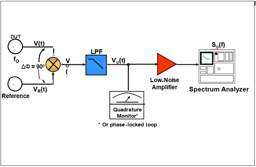
Phase Noise Measurement
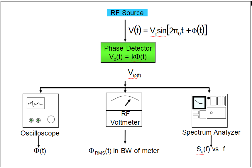
Frequency - Phase - Time Relationships


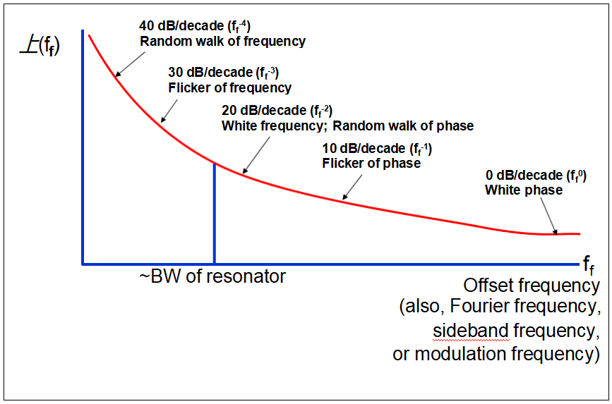
Types of Phase Noise
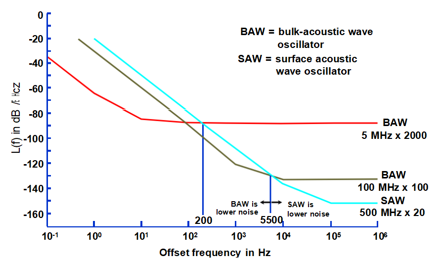
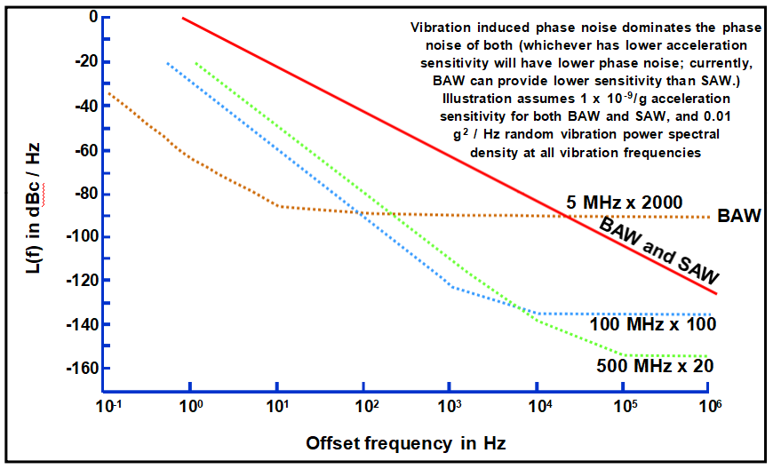
The short term stabilities of TCXOs are temperature (T) dependent, and are generally worse than those of OCXOs, for the following reasons:
• The slope of the TCXO crystal’s frequency (f) vs. T varies with T. For example, the f vs. T slope may be near zero at ~20oC, but it will be ~1ppm/oC at the T extremes. T
fluctuations will cause small f fluctuations at laboratory ambient T’s, so the stability can be good there, but millidegree fluctuations will cause ~10-9 f fluctuations at the T extremes. The TCXO’s f vs. T slopes also vary with T; the zeros and maxima can be at any T, and the
maximum slopes can be on the order of 1 ppm/oC.
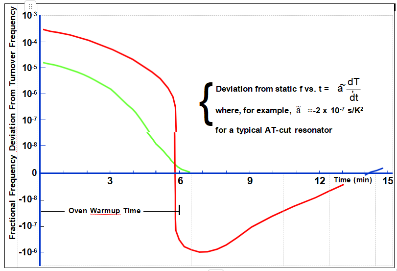
• AT-cut crystals’ thermal transient sensitivity makes the effects ofT fluctuations depend not only on the T but also on the rate of change of T (whereas the SC-cut crystals
typically used in precision OCXOs are insensitive to thermal transients). Under changing T conditions, the T gradient between the T sensor (thermistor) and the crystal will aggravate the problems.
• TCXOs typically use fundamental mode AT-cut crystals which have lower Q and larger C1 than the crystals typically used in OCXOs. The lower Q makes the crystals inherently noisier, and the larger C1 makes the oscillators more susceptible to circuitry noise.
• AT-cut crystals’ f vs. T often exhibit activity dips (see “Activity Dips” later in this
chapter). At the T’s where the dips occur, the f vs. T slope can be very high, so the noise due to T fluctuations will also be very high, e.g., 100x degradation of σy(τ) and 30 dB degradation of phase noise are possible. Activity dips can occur at any T.
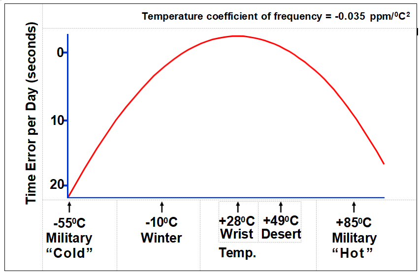
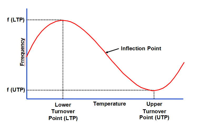
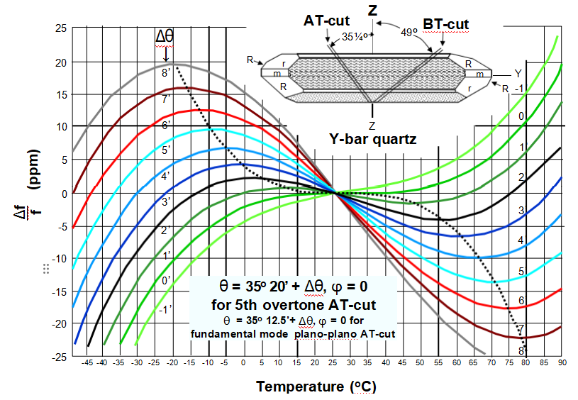
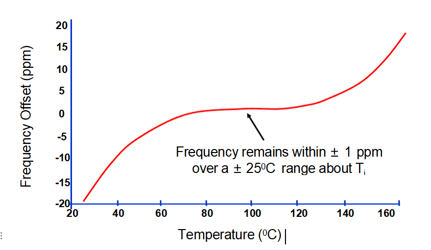
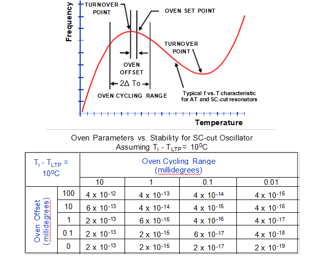
A comparative table for AT and other non-thermal-transient compensated cuts of oscillators would not be meaningful because the dynamic f vs. T effects would generally dominate the static f vs. T effects.
Oven Stability Limits
• Thermal gains of 105 has been achieved with a feed-forward compensation technique (i.e., measure outside T of case & adjust setpoint of the thermistor to anticipate and
compensate), and with double ovens. For example, with a 105 gain, if outside ΔT = 100oC, inside ΔT = 1 mK.
• Stability of a good amplifier ~ 1μK/K
• Stability of thermistors ~1mK/year to 100mK/year
• Noise < 1μK (Johnson noise in thermistor + amplifier noise + shot noise in the bridge current)
• Quantum limit of temperature fluctuations ~ 1nK
• Optimum oven design can provide very high f vs. T stability
Warmup of AT- and SC-cut Resonators
TCXO Thermal Hysteresis
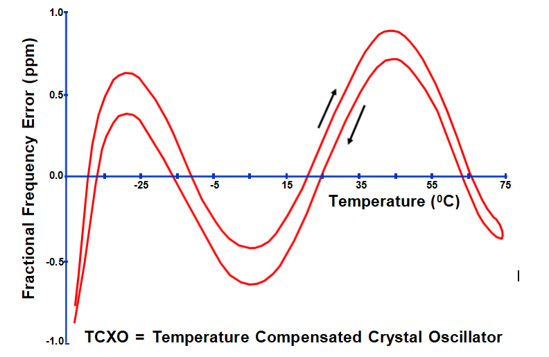
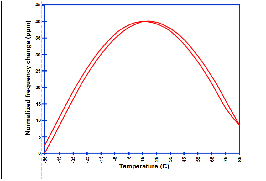
Apparent Hysteresis
OCXO Retrace
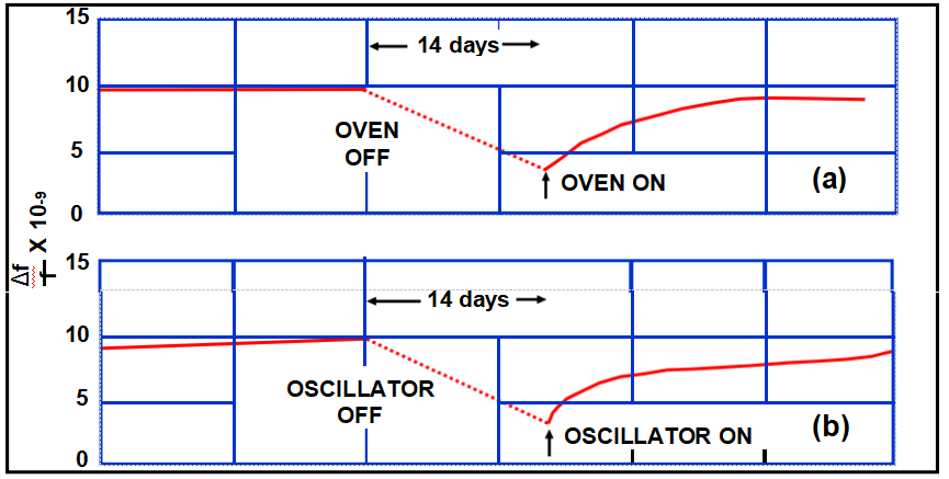
In (a), the oscillator was kept on continuously while the oven was cycled off and on. In (b), the oven was kept on continuously while the oscillator was cycled off and on.
TCXO Trim Effect
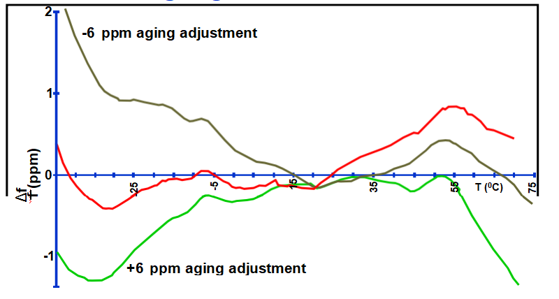
In TCXO ’s,temperature sensitive reactances are used to compensate for f vs. T
variations. A variable reactance is also used to compensate for TCXO aging. The effect of the adjustment for aging on f vs. T stability is the “trim effect” . Curves show f vs. T
stability of a “0.5 ppm TCXO,” at zero trim and at ±6 ppm trim. (Curves have been vertically displaced for clarity.)
Why the Trim Effect?

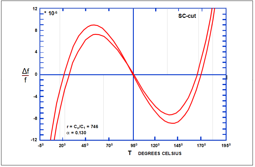
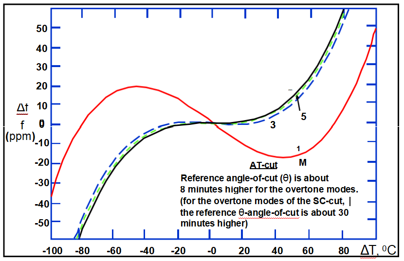
Effects of Harmonics on f vs. T
Amplitude - Frequency Effect
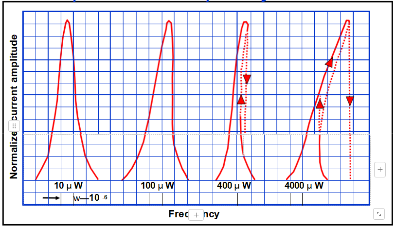
At high drive levels, resonance curves become asymmetric due to the nonlinearities of quartz.
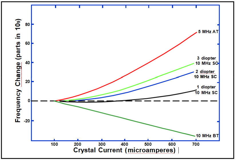
Frequency vs. Drive Level
Drive Level vs. Resistance
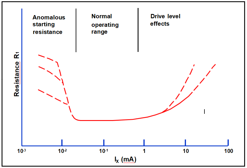
Second Level of Drive Effect
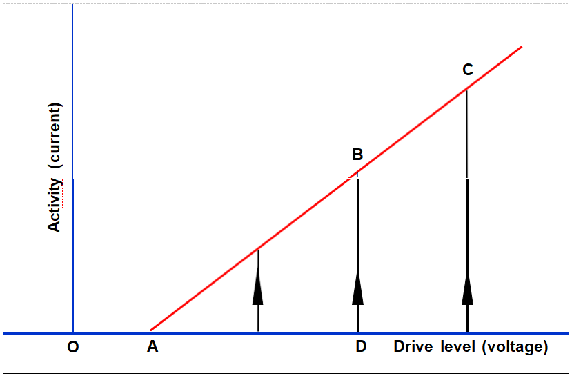
Activity Dips
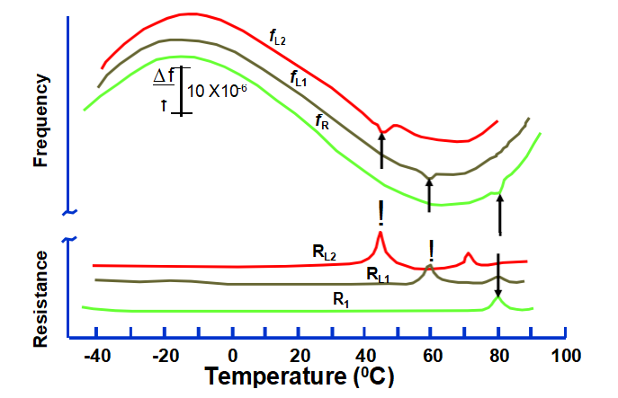
Activity dips in the f vs. T and R vs. T when operated with and without load
capacitors. Dip temperatures are a function of C L, which indicates that the dip is caused by a mode (probably flexure) with a large negative temperature coefficient.
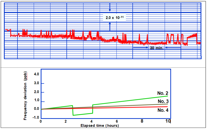
Frequency Jumps
Acceleration vs. Frequency Change
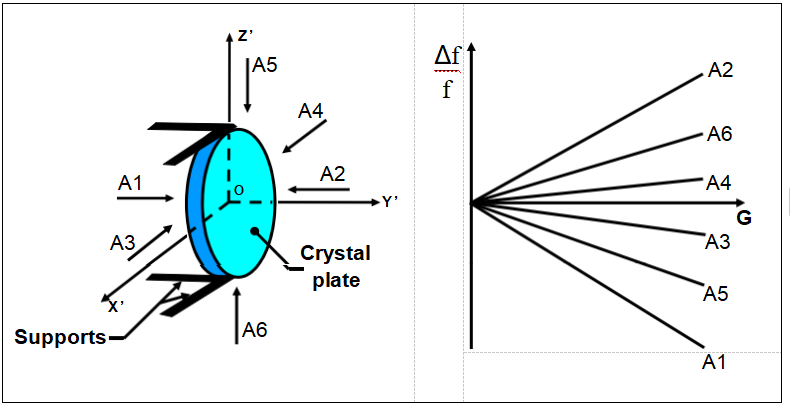
Frequency shift is a function of the magnitude and direction of the
acceleration, and is usually linear with magnitude up to at least 50 g’s.
Acceleration Is Everywhere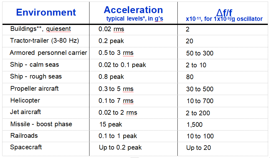
* Levels at the oscillator depend on how and where the oscillator is mounted Platform resonances can greatly amplify the acceleration levels.
** Building vibrations can have significant effects on noise measurements
Acceleration Affects “Everything”
• Acceleration Force Deformation (strain)
Change in material and device properties - to some level
• Examples:
- Quartz resonator frequency
- Amplifier gain (strain changes semiconductor band structure)
- Laser diode emission frequencies
- Optical properties - fiber index of refraction (acoustooptics)
- Cavity frequencies
- DRO frequency (strain changes dielectric constants)
- Atomic clock frequencies
- Stray reactances
- Clock rates (relativistic effects)
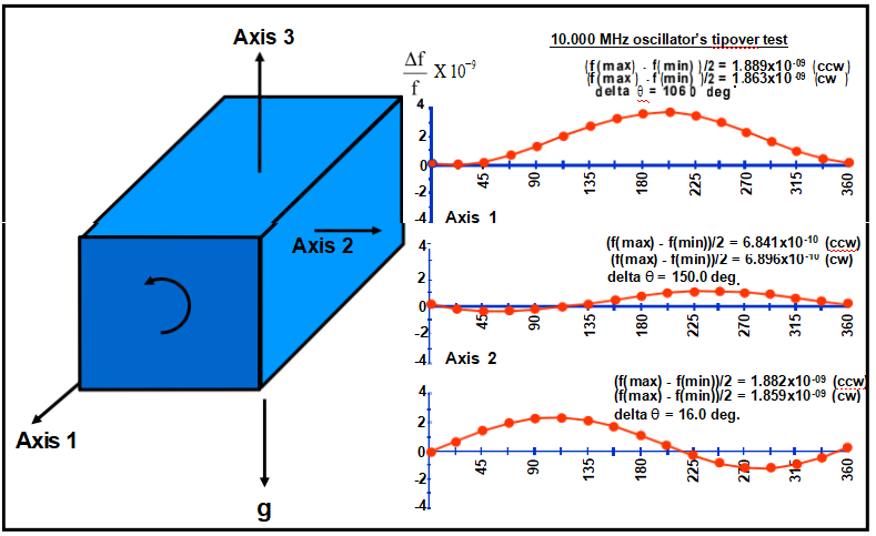
2-g Tipover Test
(Δf vs. attitude about three axes)
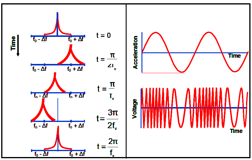
Sinusoidal Vibration Modulated Frequency
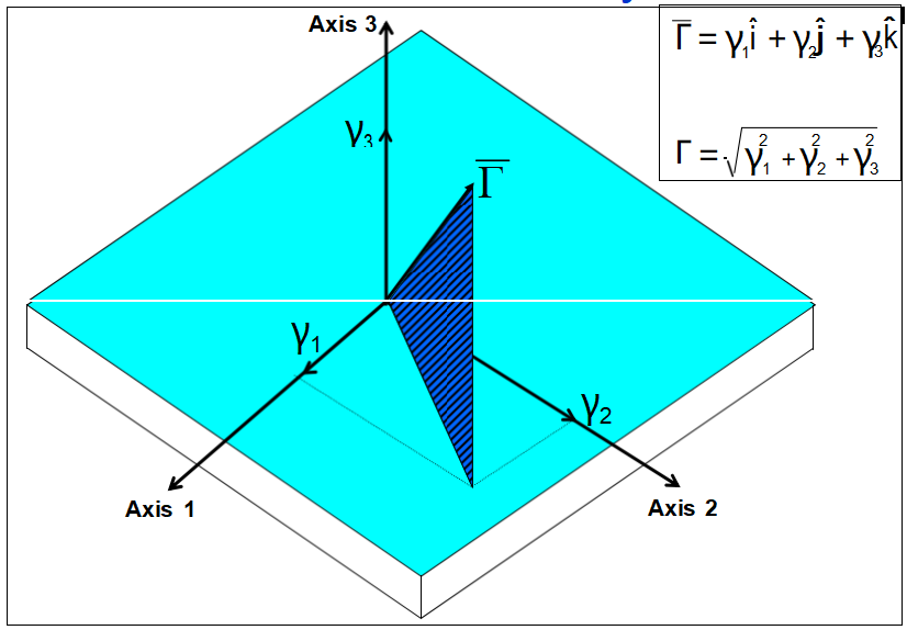
Acceleration Sensitivity Vector
Vibration-Induced Allan Deviation Degradati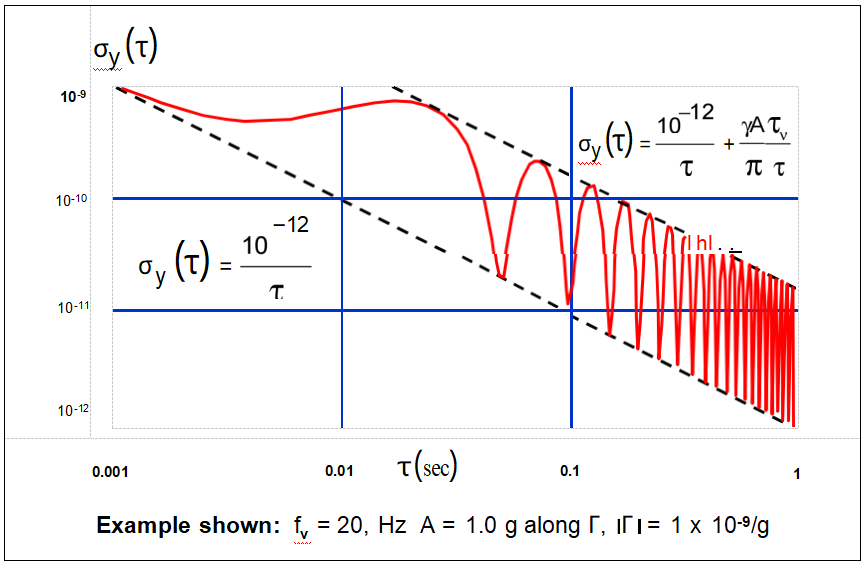
Vibration-Induced Phase Excursion
The phase of a vibration modulated signal is

When the oscillator is subjected to a sinusoidal vibration, the peak phase excursion is

Example: if a 10 MHz, 1 x 10⁻⁹/g oscillator is subjected to a 10 Hz
sinusoidal vibration of amplitude 1g, the peak vibration-induced phase excursion is 1 x 10⁻³ radian. If this oscillator is used as the reference
oscillator in a 10 GHz radar system, the peak phase excursion at 10GHz will be 1 radian. Such a large phase excursion can be catastrophic to
the performance of many systems, such as those which employ phase locked loops (PLL) or phase shift keying (PSK).
Vibration-Induced Sidebands
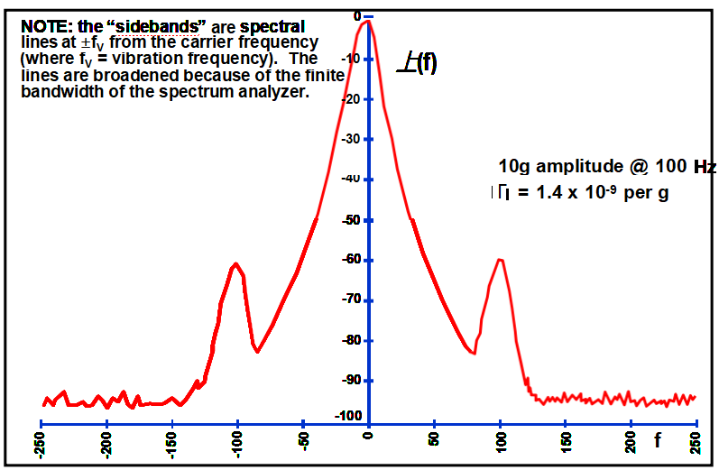
Vibration-Induced Sidebands After Frequency Multiplication


