POP_UP_MESSAGE_CONTENT


Tutorial on Frequency Control and Timing Application of Quartz Crystal Resonators and Oscillators (Part 2)
Oscillator Instabilities - General Expression

where QL = loaded Q of the resonator, and dφ(ff) is a small
change in loop phase at offset frequency ff away from carrier
frequency f. Systematic phase changes and phase noise within the loop can originate in either the resonator or the sustaining
circuits. Maximizing QL helps to reduce the effects of noise and environmentally induced changes in the sustaining electronics. In a properly designed oscillator, the short-term instabilities are determined by the resonator at offset frequencies smaller than the resonator’s half-bandwidth, and by the sustaining circuit and the amount of power delivered from the loop for larger offsets.
Instabilities due to Sustaining Circuit
• Load reactance change - adding a load capacitance to a crystal changes the frequency by
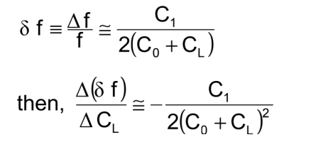
• Example: If C0 = 5 pF, C1 = 14fF and CL = 20pF, then a ΔCL = 10 fF
(= 5 X 10⁻⁴) causes ≈ 1 X 10⁻⁷ frequency change, and a CL aging of
10 ppm per day causes 2 X 10⁻⁹ per day of oscillator aging.
• Drive level changes: Typically 10-8 per ma2 for a 10 MHz 3rd SC-cut.
• DC bias on the crystal also contributes to oscillator aging.
Oscillator Instabilities - Tuned Circuits
Many oscillators contain tuned circuits - to suppress unwanted modes, as matching circuits, and as filters. The effects of small changes in the tuned circuit's inductance and capacitance is given by:

where BW is the bandwidth of the filter, ff is the frequency offset of the center frequency of the filter from the carrier frequency, QL is the loaded Q of the resonator, and Qc, Lc and Cc are the tuned circuit's Q, inductance and capacitance, respectively.
Oscillator Instabilities - Circuit Noise
Flicker PM noise in the sustaining circuit causes flicker FM contribution to the oscillator output frequency given by:
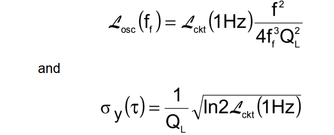
where ff is the frequency offset from the carrier frequency f, QL is the loaded Q of the resonator in the circuit, 上ckt (1Hz) is the flicker PM noise at ff = 1Hz, and τ is any measurement time in the flicker floor range. For QL = 106 and 上ckt (1Hz) = -140dBc/Hz, σy(τ ) = 8.3 x 10⁻¹⁴ . ( 上ckt (1Hz) = -155dBc/Hz has been achieved.)
Oscillator Instabilities - External Load
If the external load changes, there is a change in the amplitude or phase of the signal reflected back into the oscillator. The
portion of that signal which reaches the oscillating loop changes the oscillation phase, and hence the frequency by

where Γ is the VSWR of the load, and θ is the phase angle of the reflected wave; e.g., if Q ~ 106 , and isolation ~40 dB
(i.e., ~10-4), then the worst case (100% reflection) pulling is
~5 x 10⁻⁹ . AVSWR of 2 reduces the maximum pulling by only a factor of 3. The problem of load pulling becomes worse at higher frequencies, because both the Q and the isolation are lower.
Oscillator Outputs
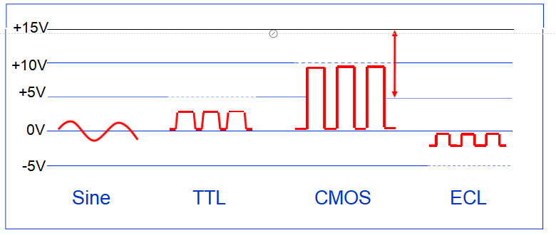
Most users require a sine wave, a TTL-compatible, a CMOS- compatible, or an ECL-compatible output. The latter three can be simply generated from a sine wave. The four output types are
illustrated below, with the dashed lines representing the supply
voltage inputs, and the bold solid lines, the outputs. (There is no “standard” input voltage for sine wave oscillators. The input
voltages for CMOS typically range from 1V to 10V.)
Why Quartz?
Quartz is the only material known that possesses the following combination of properties:
• Piezoelectric ("pressure-electric"; piezein = to press, in Greek)
• Zero temperature coefficient cuts exist
• Stress compensated cut exists
• Low loss (i.e., high Q)
• Easy to process; low solubility in everything, under "normal" conditions, except the fluoride and hot alkali etchants; hard but not brittle
• Abundant in nature; easy to grow in large quantities, at low cost, and with relatively high purity and perfection. Of the man-grown single crystals, quartz, at ~3,000 tons per year, is second only to silicon in
quantity grown (3 to 4 times as much Si is grown annually, as of 1997).
The Piezoelectric Effect

The piezoelectric effect provides a coupling between the mechanical properties of a piezoelectric crystal and an electrical circuit.
The Piezoelectric Effect in Quartz
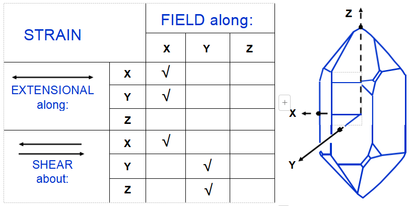
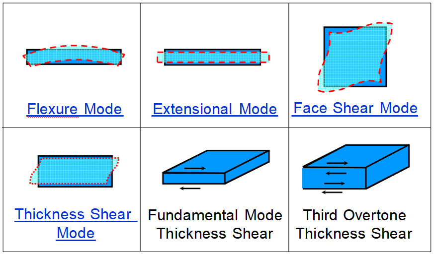
In quartz, the five strain components shown may be generated by an electric field. The modes shown on the next page may be excited by suitably placed and shaped electrodes. The shear strain about the Z-axis produced by the Y-component of the field is used in the rotated Y-cut family, including the AT, BT, and ST-cuts.
Modes of Motion
(Click on the mode names to see animation.)
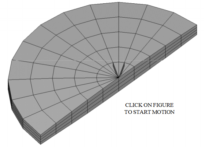
Motion Of A Thickness Shear Crystal
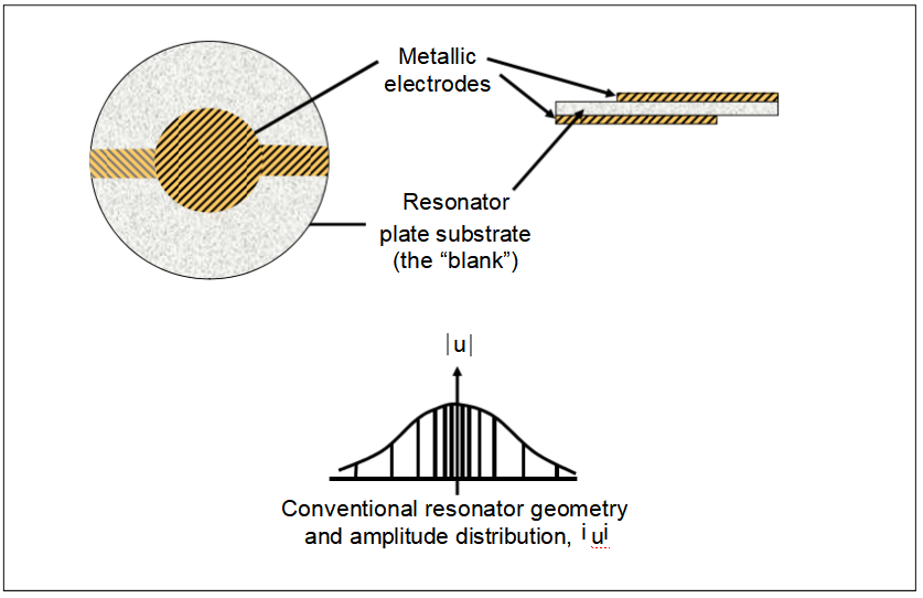
Resonator Vibration Amplitude Distribution
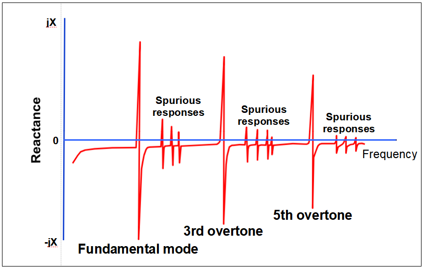
Overtone Response of a Quartz Crystal
Quartz is Highly Anisotropic
l The properties of quartz vary greatly with crystallographic direction.
For example, when a quartz sphere is etched deeply in HF, the
sphere takes on a triangular shape when viewed along the Z-axis, and a lenticular shape when viewed along the Y-axis. The etching rate is
more than 100 times faster along the fastest etching rate direction (the Z-direction) than along the slowest direction (the slow-X-direction).
l The thermal expansion coefficient is 7.8 x 10⁻⁶/。C along the Z- direction, and 14.3 x 10⁻⁶/。C perpendicular to the Z-direction; the temperature coefficient of density is, therefore, -36.4 x 10⁻⁶/。C.
l The temperature coefficients of the elastic constants range from -3300 x 10-6/。C (for C12) to +164 x 10-6/。C (for C66).
l For the proper angles of cut, the sum of the first two terms in Tf on the previous page is cancelled by the third term, i.e., temperature
compensated cuts exist in quartz. (See next page.)


