POP_UP_MESSAGE_CONTENT


The Evaluation Method for Oscillatory Circuits (2): The Work Conducted to Evaluate Oscillatory Circuits (Chapter on Oscillatory Margin and Excitation Power)
【1】 Evaluation of oscillation margin (negative impedance)
Inserting impedance into the HOT terminal of a quartz crystal unit and detecting whether it starts oscillating (testing negative impedance RN) is a simple method to evaluate the negative impedance characteristics and oscillation margin of an oscillating circuit. The ability of an oscillating circuit can be tested by changing the impedance value of the insertion (the magnitude of the loss).
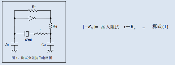
Figure 1 is a circuit diagram for testing negative impedance. The absolute value of negative impedance is equal to the sum of the inserted impedance value r and the equivalent impedance (Re) when the quartz crystal unit is connected to the load. Equation (1)

The equivalent impedance (Re) of a quartz crystal unit connected to a load can be calculated using the following equation (2).
R1 is the equivalent series impedance of a quartz crystal unit without load capacitance.

The quartz crystal unit constant (R1=33.7 Ω C0=1.11pF、CL=7.8pF), After substituting the above equation (2), the equivalent impedance (Re) can be calculated to be 44 Ω.
At this point, R1 is the measured value of the quartz crystal unit, not the parameter value. Assuming the maximum value of R1 is 57 Ω, Re is affected by the load capacitance
Increase to 74 ohms, please note.

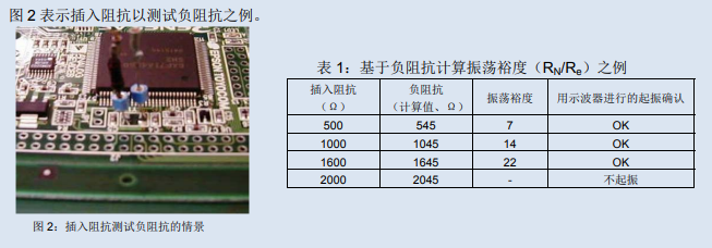
Confirm the waveform with an oscilloscope in the state shown in Figure 2. Gradually increase the inserted impedance value r and search for impedance points that do not vibrate. At this point, ignore the decrease in oscillation output and changes in oscillation frequency caused by impedance insertion, and only determine whether oscillation has occurred.
After determining the negative impedance RN, calculate the oscillation margin RN/Re (as shown in Table 1 above).
It should be noted that a low oscillation margin will cause various adverse phenomena, such as unstable oscillation, failure to start oscillation, or longer oscillation time due to uneven circuit characteristics.
When the oscillation margin is more than 5 times, it means that the oscillation circuit has sufficient ability to excite the quartz crystal unit (amplification), and usually no problems occur. If the oscillation margin is below 5 times, it is recommended to change the circuit constant of the oscillation circuit, increase the negative impedance RN, or reduce the equivalent series impedance Re of the quartz crystal unit to maintain the oscillation margin above 5 times.
Although reducing the circuit constant of oscillation circuits such as fine-tuning capacitors (Cg, Cd) or current limiting resistors (Rd) can increase negative impedance and oscillation margin, it should be noted that the load capacitance of oscillation circuits changes with the circuit constant, which will also cause a change in oscillation frequency. To reduce the equivalent series resistance R1 of quartz crystal units, it is necessary to make a request to the quartz crystal manufacturer.
【2】 Evaluation of Incentive Power
Excitation power refers to the electricity consumed by the oscillation of quartz crystal units. Usually, the excitation power is best controlled within the specification parameters of the quartz crystal unit, generally below about 100 μ W, but it should be noted that there are slight differences among quartz crystal manufacturers.
When the excitation power is too high, it will cause fluctuations in oscillation frequency, decreased stability, changes in equivalent circuit parameters, or frequency distortion. High excitation power may also lead to repeated abnormal oscillations and the consequences of faults. Calculate the excitation power (P) using the following equation (3).

Here, I is the current flowing through the quartz crystal unit, and Re is the equivalent resistance of the quartz crystal unit under load. If the excitation power exceeds the specification parameters, it is necessary to adjust the constant of the oscillation circuit to reduce the current flowing through the quartz crystal unit. Reducing Cg or Cd can decrease the excitation power, but the load capacitance of the oscillation circuit will also change accordingly. The simplest method is to increase Rd, but the loss will increase and the negative impedance will decrease accordingly.The excitation power cannot be directly measured.
Place the test needle on the HOT terminal of the quartz crystal unit combined with the oscillation circuit, use an oscilloscope to test the applied voltage Vpp, and calculate the current flowing through the quartz crystal unit based on the measured value.
Figure 3 shows the scenario when testing the excitation power.
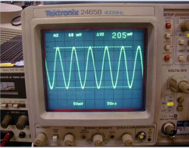
After inserting the current probe into the terminal of the quartz crystal unit for evaluation, install it onto the quartz crystal unit of the printed board. After confirming the oscillation through an oscilloscope, measure Vpp based on the waveform.

Figure 3: Scenario for testing excitation power
For example, assuming that Vpp=0.205V is obtained from the waveform of the oscilloscope, the test probe is set to 1mA/div, the probe impedance is 50 Ω, the test range of the oscilloscope is 50mV/div, and the equivalent resistance Re of the quartz crystal unit with load is 45 Ω, then
Vpp/50[mV/div]=205/50=4.1div
4.1/(2√2)=1.45div
50[mV/div]/50Ω=1mA/div,
From this, the current I flowing through the quartz crystal unit is 1.45div × 1mA/div=1.45mA.
According to equation (3) on the previous page, the excitation power P is calculated to be 1.45 × 1.45 × 45=95 μ W.
【3】 Conclusion
We explained the evaluation method of oscillating circuits twice. To make the best oscillating circuit, it is necessary to optimize (1) frequency matching, (2) oscillation margin (negative impedance), and (3) excitation power separately.
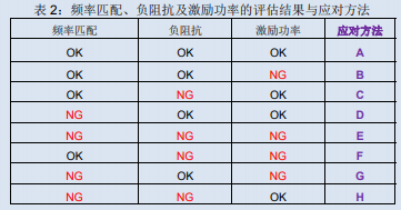
Although setting the optimal circuit constant for any of the above is the most ideal approach, there may also be situations where it is not suitable in practical work. We have summarized the response methods at this point in the end.

A. Use the circuit constants used for evaluation.
B. We need to review the specifications and parameters of the quartz crystal unit regarding the excitation power. Please confirm whether the excitation power of this evaluation result affects quartz crystals
Body unit.
C. Need to review the specifications and parameters of quartz crystal units related to negative impedance. Please consider whether it is possible to change the specification of the equivalent series impedance of the quartz crystal unit
Parameter R1, to achieve oscillation margin of more than 5 times.
D. Regarding frequency matching, it is necessary to consider adjusting the predetermined standard load capacitance to the actual load capacity of the substrate on which the quartz crystal unit is assembled
Rong.
E. It is necessary to adopt a combination of "B+C+D" as a response method.
We need to adopt a combination of "B+C" to cope with F.
G requires a combination of "B+D" response methods.
H requires a combination of "C+D" response methods.
I hope that the information from last time and this time can serve as a reference for designing highly reliable oscillation circuits.


