POP_UP_MESSAGE_CONTENT


High precision timing using real-time clock module
Explanation of Epson Real Time Clock Module with Time Adjustment Function below Seconds
[Preface]
In recent years, with the popularity of radio watches and the ability to obtain standard time from NTP time servers, obtaining extremely accurate time is no longer tedious and laborious. Therefore, the design of application systems for finance, transportation management, power control, safety, and sports is generally based on a reference to the correct time. This type of processing system must be equipped with numerous terminal devices in the data input and output sections, and these terminal devices also need to have the correct timing. In response to the above demand, Epson has provided the market with built-in high stability frequency Real time clock module for oscillating quartz crystal units.
In this product group, high-precision products with built-in TCXO digital real-time clock module and temperature compensation function are as follows: RX-4803SA/LC, RA4803SA (serial interface, hereinafter referred to as "4803 series") and RX-8803SA/LC, RA8803SA (I2C interface, hereinafter referred to as "8803 series"). These products can maintain frequency output accuracy within a temperature range of -40 to+85 ℃ at ± 3.4 × 10⁻⁶ (equivalent to a monthly difference of 9 seconds), which means the average time error per day is controlled below ± 0.3 seconds.
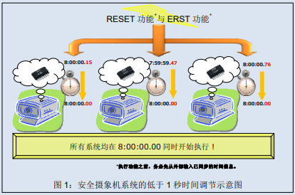
However, even though the above products have high time accuracy, some customers still require adjustments for small errors below 1 second due to usage needs. The principle of the real-time clock module generating 1 second is to use a 32.768kHz quartz crystal unit as the wave source and obtain it through frequency division. If multiple devices need to perform a certain action simultaneously, it is necessary to adjust the error of less than 1 second to keep the time of each device consistent. The 4803 series and 8803 series products can adjust an error of less than 1 second in response to this demand.
Many Epson real-time clock modules are equipped with a RESET function, which can be adjusted using software for errors below 1 second. However, using software to adjust time may result in time deviation due to software processing time. For users who require precise synchronization, this error also needs to be addressed. For this reason, the 4803 series and 8803 series are equipped with ERST function that uses hardware to adjust the time.
This article explains the built-in TCXO digital real-time clock module 4803 series and 8803 series equipped with RESET and ERST functions for adjusting time below 1 second, and uses timing diagrams and other examples to illustrate.

【High precision timing method using Epson real-time clock module (adjustment below 1 second)】
The 4803 series and 8803 series Epson real-time clock modules can use the following two methods to achieve high-precision adjustment for time less than 1 second:
1. Using RESET timing: timing method for application software
2. Using ERST timing: a timing method for application hardware
The following text provides a detailed explanation of the registers, reset actions, and setting examples related to using the two time synchronization methods mentioned above. Before using the above method, be sure to input synchronized time information from external sources.
1. Use RESET bit for timing example
The RESET bit synchronization performed by software can adjust the time by operating the registers of the real-time clock module. In addition to the 4803 and 8803 series, many Epson real-time clock module products use this technique.
·Associated Register
4803 series (Bank1, 2)

·RESET bit and action description (including timing diagram)
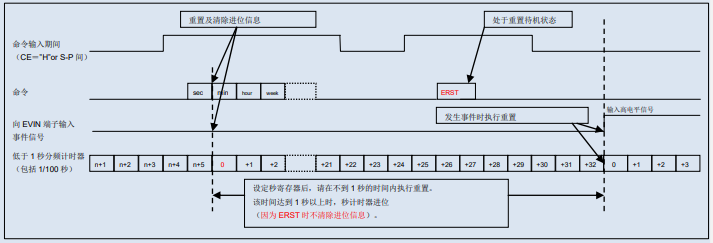
After the RESET bit is set to "1", the timer of the timing circuit that is less than 1 second will be reset at the end of the command. To start accurate timing at a specific time, you can reset it after the set time, and then update the second timer every second.

·Notes on using the RESET bit
The RESET bit executes actions under the following prerequisites:
Only set the RESET bit to "1", and the timer will not stop (continue counting);
Reset is relatively independent of other commands and acts independently. After writing the RESET bit, the timer that is less than 1 second after the command input ends is reset.
When performing a reset, do not clear the carry information. Therefore, please reset the timer below 1 second within less than 1 second after setting the second register;
2. Use ERST timing examples
The ERST bit timing performed by hardware can be adjusted by setting registers in advance and inputting event signals to regulate the time. Compared with the previous explanation of using RESET bit synchronization, this method does not generate time deviation due to software processing time, thus enabling more accurate synchronization.
·Associated Register
4803 series (Bank3)

·ERST bit and action description (including timing diagram)
After setting the ERST bit to "1", the timer of the timing circuit that is less than 1 second will be reset at the same time as detecting external events input to the EVIN terminal. To start accurate timing at a specific time, you can input an event to the EVIN terminal after the set time, and then update the second timer every second. When the EHL bit is "0", the event detection result of the input signal to the EVIN terminal is low level; When the EHL bit is set to "1", a high level (* a) is detected. The following is an example of the action when the EHL bit is set to "1" (high level detected).

·Attention points when using ERST position
ERST performs actions under the following conditions:
Only set the ERST bit to "1", and the timer will not stop (continue counting);
ERST is relatively independent of other commands and operates independently. After writing the ERST bit, the timer for input events that are less than 1 second is reset;
When executing ERST, do not clear carry information. Therefore, reset the timer below 1 second within less than 1 second after setting the second register;
After setting the ERST bit to "1", as long as the ERST bit is set to "0" before the event occurs, the ERST function can be disabled.
(* a) High precision real-time signal detection does not remove input skip, but the minimum pulse width holding time must be at least 367 microseconds to achieve synchronization between timing actions and EVIN terminal inputs in the internal clock.
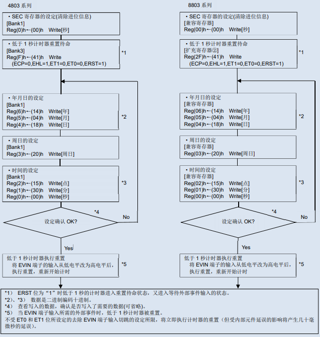
·Example of high-precision timing setting using ERST bits
Example of Time and Calendar Setting [Setting Value: April 18, 2014 [Friday] 15:30:00]

·High precision time setting synchronized with 1PPS signal
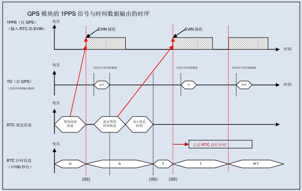
Hardware timing using ERST bits can also use 1PPS signals (pulses per second, 1Hz output signal) from GPS modules and other sources as external event inputs to receive accurate time signals from GPS for high-precision timing.
The following example is a timing diagram of the 1PPS signal output by the GPS module and the time data output.

Please note that this function may not accurately synchronize in environments where the GPS module cannot receive satellite information correctly.
As stated so far, Epson will not only provide customers with high-performance (=clock accuracy) real-time clock modules, but also offer products equipped with the functions required by customers to help build high-precision synchronous time processing systems. Moreover, Epson's real-time clock module has been adjusted for frequency accuracy before leaving the factory, and is provided to customers on the basis of ensuring accuracy. Therefore, there is no need to adjust the frequency during use, which contributes to improving design efficiency and product quality for customers.


