POP_UP_MESSAGE_CONTENT


What is an IMU and how it works
IMU is mainly used for devices that require motion control, such as cars and robots. It is also used in situations that require precise attitude displacement estimation, such as inertial navigation equipment for submarines, aircraft, missiles, and spacecraft.
High precision and stable control of MEMS IMU
The use of three-axis geomagnetic decoupling and three-axis accelerometer is greatly affected by external force acceleration. In motion/vibration environments, there is a significant error in the output direction angle. This type of magnetic field sensor has its drawbacks. Its absolute reference point is the magnetic field line of the geomagnetic field. The characteristic of geomagnetism is its wide range of applications, but its intensity is relatively low, about one tenth of Gaussian, and it is easily disturbed by other magnets. If combined with the instantaneous angle of the z-axis gyroscope, the system data can be more stable. Acceleration is measured in the direction of gravity. In the absence of external acceleration, the roll/pitch two axis attitude angles can be accurately output, and there is no cumulative error in this angle, which is accurate over a longer time scale. However, the disadvantage of accelerometers in measuring angles is that they actually use MEMS technology to detect small deformations caused by inertial forces, which are essentially the same as gravity. Therefore, accelerometers do not distinguish between gravitational acceleration and external force acceleration. When the system changes speed in three-dimensional space, its output is incorrect
The output angular velocity of a gyroscope is an instantaneous quantity and cannot be directly used for attitude balance. Calculating angles requires angular velocity and time integration. Add the obtained angle change to the initial angle to obtain the target angle. The smaller the integration time DT, the more accurate the output angle. However, the working principle of the gyroscope determines that its measurement reference is itself, and there is no absolute reference outside the system. In addition, DT cannot be infinitely small, so the accumulated error of integration will rapidly increase over time, resulting in output angles that are inconsistent with reality. Therefore, the gyroscope can only operate in a shorter time scale.
Therefore, without any other reference, in order to obtain a more realistic attitude angle, we should use weighted algorithms to leverage strengths and avoid weaknesses, combine the advantages of both, discard their respective shortcomings, and design an algorithm to increase the weight of the gyroscope in the short time scale and the speed weight in the long time scale, so that the system output angle is close to the true value.
Working principle of IMU
IMU is a strapdown inertial navigation system. The system consists of three acceleration sensors and three angular velocity sensors (gyroscopes). Accelerometers are used to sense the acceleration component of the aircraft relative to the vertical line on the ground, while velocity sensors are used to sense the angle information of the aircraft. This sub device mainly consists of two A/D converters ad7716b and a 64Ke/eprom memory X25650. The A/D converter utilizes the analog variables of various sensors in the IMU to convert them into digital information. After calculation by the CPU, it outputs the pitch angle, tilt angle, and sideslip angle. The e/eprom memory mainly stores the linear curve diagrams of each IMU sensor and the part and serial numbers of each IMU sensor. When the part is first started, the image processing unit reads the linear curve parameters in e/eprom to provide initial information for subsequent angle calculations.
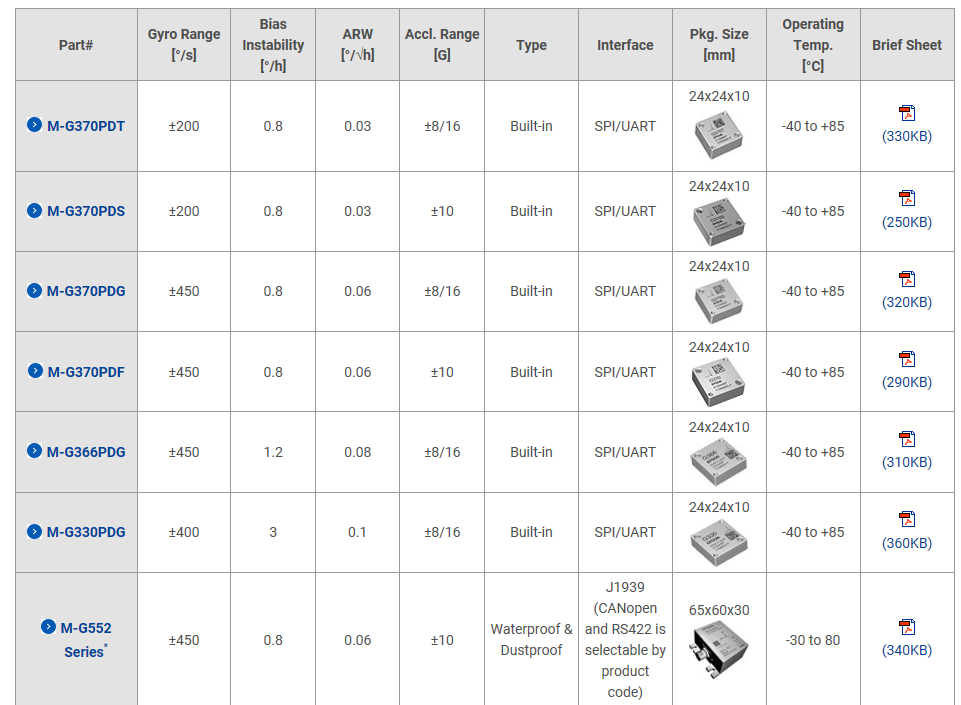
IMU Recommended Product Comparison Table:


