POP_UP_MESSAGE_CONTENT


Fundamentals of Radio Frequency Knowledge: Introduction to Three Types of Receptors

Figure 1 Superheterodyne structure of first-order mixing
The superheterodyne structure of single-stage mixing is shown in Figure 1, where the mixer down converts the RF signal to the IF frequency using the local oscillator signal. The superheterodyne structure consists of the following modules: input bandpass filter, low noise amplifier, image suppression filter, mixer, intermediate frequency filter, AD。
Input bandpass filters are commonly used to suppress out of band interference signals and prevent strong out of band interference signals from blocking low-noise amplifiers. Usually, input bandpass filters have a wide bandwidth and are composed of multiple channels. Mirror filters are used to suppress mirror frequencies. We will provide a detailed introduction to mirror filters below. The IF bandpass filter after mixing determines the channel selectivity of the receiver, which is used to suppress the power of adjacent channel signals. At the same time, the IF bandpass filter is usually used as an anti aliasing filter in the AD front-end.
homodyne receiver
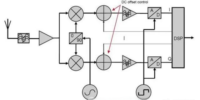
The main problem that superheterodyne receivers need to solve is the problem of image frequency suppression. The zero intermediate frequency receiver overcomes the problem of image suppression by directly converting the signal to baseband (0Hz). Its structure is as follows:

Figure 2 Structure of Zero IF Receiver
The local oscillator frequency (LO) of the zero intermediate frequency receiver is equal to the radio frequency signal frequency (RF), and the image frequency is the signal frequency itself. There is no problem of image frequency interference, and the image suppression filter and intermediate frequency filter in the original superheterodyne receiver structure can be omitted. On the one hand, eliminating external components is beneficial for the single-chip implementation of the system.
As shown in Figure 2, there is an analog low-pass filter behind the mixer, which serves as a channel selection filter and an anti aliasing filter for the AD front-end. If the channel selectivity of the receiver is entirely achieved by the filter, then the cut-off frequency of the filter is required to be half of the signal bandwidth to effectively suppress interference from adjacent channels and more distant channels.
Since the filter operates at low frequencies, it can be implemented using an active analog filter, paying attention to matching the amplitude response of the upper and lower branches. Active analog filters have limited input dynamic range and limited stopband attenuation compared to passive intermediate frequency filters in superheterodyne reception.
Although the zero intermediate frequency receiver structure reduces the problem of image signal suppression, it also brings other issues. These issues are mainly due to the amplification group of the input signal being concentrated in the baseband. These issues include: 1. Even order nonlinear distortion of the receiver; 2. Local oscillator leakage and DC bias; 3. DC bias; 4. Flicker noise.
low-if receiver
Low intermediate frequency receivers attempt to solve the DC bias and flicker noise problems of zero intermediate frequency receivers, while maintaining high integration of zero intermediate frequency receivers. Many wireless standards require relatively weaker suppression of adjacent channel interference compared to interference from other channels. Low to intermediate frequency receivers make full use of such regulations by selecting appropriate intermediate frequency frequencies to use adjacent channel signals as their image signals.

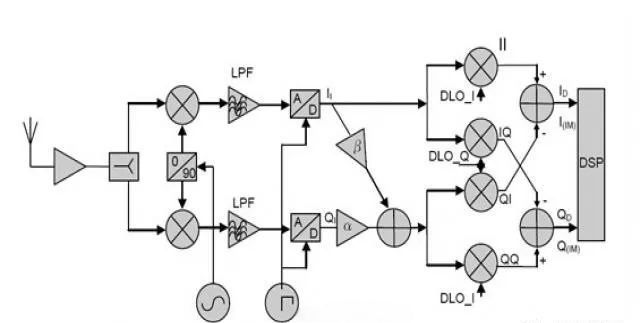
Figure 3 Structure of Low and Medium Frequency Receiver
The signal undergoes first stage mixing and outputs a low to intermediate frequency signal. I. The Q two signals are passed through a low-pass filter (anti aliasing filter) and then sampled. As mentioned earlier, due to the mismatch in amplitude and phase between the I and Q channels, it is difficult to achieve a mirror suppression ratio exceeding 40dB. If no correction is performed, a mirror suppression ratio of 25dB to 35dB can be obtained. As shown in the figure, there is a correction branch consisting of two amplifiers and an addition circuit behind the AD, which can significantly improve the image suppression ratio.


