


PROBLEM?
+86 13430584894
luojunjie@piezoman.com
PAYMENT_METHOD


 AD_MSG
POP_UP_MESSAGE_CONTENT


【1】 Preparation before evaluating oscillation frequency (frequency matching)
Generally, quartz crystal manufacturers use the three data points proposed by the circuit designer, namely the quartz crystal unit oscillation frequency (FL), load capacitance (CL value), and oscillation frequency tolerance error (Δ f), to start the crystal unit oscillation based on the load capacitance (CL value), and adjust the oscillation frequency and tolerance error.
It should be noted that the pre specified load capacitance (CL value) does not take into account the capacitance (stray electricity) generated by various factors in the actual substrate
Rong). Stray capacitance is one of the factors causing a decrease in oscillation frequency accuracy, so its impact should be considered. Either the quartz crystal manufacturer should change the oscillation frequency of the quartz crystal unit, or the circuit designer should readjust the stray capacitance. This is the general framework of oscillation frequency matching work.
【2】 Evaluation of oscillation frequency (frequency matching)
Let's start the actual evaluation work here.
Firstly, confirm the oscillation frequency of the quartz crystal unit (evaluation crystal unit) and the oscillation circuit installed together on the substrate.
This is called 'confirming frequency matching status'. Mastering the difference between the oscillation frequency when installed on the substrate and the oscillation frequency when using a standard load capacitor can confirm the deviation between the actual capacitance (circuit side capacitance) of the substrate and the pre specified standard capacitance. The substrate capacitance referred to here includes the capacitance (load capacitance) when observing the oscillation circuit from the quartz crystal unit, as well as the stray capacitance caused by the conductive pattern of the substrate.
Next, prepare the testing instruments required to evaluate the matching between the quartz crystal unit and the oscillation circuit.
The basic testing instruments required for evaluation include DC power supply, frequency meter, oscilloscope, FET probe, and current probe. Figure 1 shows an example of the basic composition of the testing instrument.
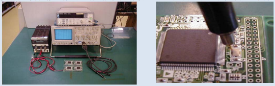
Figure 1: Basic composition of testing instruments required for evaluating frequency matching Figure 2: Place the FET probe on the HOT terminal of the quartz crystal unit to confirm the oscillation waveform
Firstly, place the FET probe on the HOT terminal of the quartz crystal unit (Figure 2), and the oscilloscope will display the waveform, while the frequency meter will display the frequency.
For example, when the oscillation frequency (Fr) of a quartz crystal unit without considering the load capacitance is 12MHz, if the oscillation frequency (FL) of its standard load capacitance is 12.000034MHz, assuming that the oscillation frequency (FR) obtained by actual testing using an FET probe after installing the quartz crystal unit on the substrate is 12.000219MHz, the difference between the oscillation frequency (FR) of the quartz crystal unit installed on the substrate and the oscillation frequency of the quartz crystal unit under the standard load capacitance is+185Hz, resulting in a difference of+15.4ppm.
The closer this difference is to zero, the higher the frequency accuracy.
There are two methods to make the difference between FR and FL close to zero.
The first method is to purchase quartz crystal units with an oscillation frequency (center frequency) offset by+15.4ppm from the quartz component manufacturer. Another method is to finely adjust the load capacitance of the oscillation circuit to obtain the corresponding oscillation frequency.
In the next item, we will introduce the matching method for micro adjusting the load capacitance.
【3】 Method of fine-tuning load capacitance to match frequency
The aforementioned data is required for calculating the load capacitance.
·Equivalent circuit constant of quartz crystal unit (Fr R1、C1、L1、C0)
·The oscillation frequency (FR) after installation on the substrate
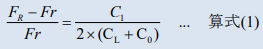
Calculate the load capacitance (CL) using the following formula based on these data.
The specific calculation example is as follows:
Assuming the rated frequency of the quartz crystal unit is 12MHz and the load capacitance (CL) of the oscillation circuit is 7.8pF.
The rated frequency here refers to the oscillation frequency (FL) under the conditions of using an oscillating circuit with a specified load capacitor.
Assuming that the quartz crystal unit was tested using a network analyzer and the following constants were obtained:
FR=12.000219 MHz
Fr=11.998398 MHz
R1=33.7 ohm
L1=70.519 mH
C1=2.495 fF
C0=1.11 pF
Here it is reiterated that Fr is the oscillation frequency of the quartz crystal unit itself. By substituting these constants into equation (1), we can obtain CL=7.11pF.
The difference between the calculated value and the previously specified oscillation circuit load capacitance (CL) of 7.8pF is 0.69pF. As long as the difference is adjusted to zero, the predetermined load capacitance of the oscillation circuit will be equal to the capacitance when the quartz crystal unit is installed on the printed circuit board.
Therefore, theoretically, the frequency tolerance also becomes zero, and the predetermined oscillation frequency can be obtained.
When actually adjusting the load capacitance of the oscillation circuit, the Cg and Cd in Figure 3 will be changed to meet the pre specified standard capacitance. At this point, the approximate values of Cg and Cd can be calculated using the following equation (2).
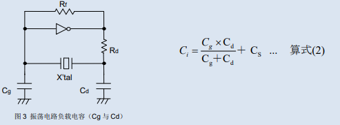
Here, Ci represents the actual load capacitance (CL) of the oscillation circuit, while Cs represents the wire pattern of the printed circuit board and the parasitic capacitance of the components. Ci only needs to be equal to the pre specified standard capacitance CL (crystal unit cell capacitance CL), so it can be calculated using the following equations (3) and (4).
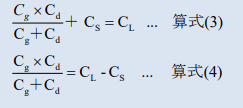
Cg and Cd are the values obtained by subtracting Cs from the specified load capacitance of a single crystal unit. The calculated values are only approximate. It is recommended to confirm the oscillation frequency while performing frequency matching when adjusting Cg and Cd in practice.
If the Cg and Cd of the oscillation circuit are difficult to change, frequency matching can be achieved by adjusting the load capacitance of the crystal unit. In this case, the quartz crystal unit manufacturer can adjust the crystal unit capacitance to circuit capacitance before purchasing, and then conduct matching evaluation to confirm the results. However, it should be noted that the load capacitance of the circuit is inversely proportional to the change in oscillation frequency. Therefore, when the load capacitance of the oscillation circuit is small, it is easily affected by small changes in the characteristics of the oscillation circuit, resulting in a deterioration of frequency stability. So, the key is to set appropriate conditions based on the purpose of the machine.