POP_UP_MESSAGE_CONTENT


The method of obtaining high-frequency output using PLL technology
[Preface]
In recent years, with the popularization of image transmission and other technologies, the amount of communication flowing through backbone networks has increased and decreased, and the high-speed and high-capacity development of communication has progressed rapidly. In this situation, there is a strong demand for high-frequency and stable output signal reference signal sources in high-speed communication infrastructure.
Usually, when obtaining high-frequency oscillations from AT type quartz crystals in the MHz frequency band, the quartz plate needs to be processed very thin (because the frequency of AT type quartz crystals depends on their thickness), which results in limitations in processing methods, mechanical strength, and susceptibility to vibration. Although it will be affected by processing accuracy, the upper limit of quartz crystals when oscillating at high frequencies based on the fundamental wave is generally around 60MHz. Therefore, our company designates frequencies above 60MHz as the high-frequency domain. Stable output of high-frequency reference signals is not simple. Epson has four methods (technologies) to achieve high-frequency field: the first method is to use an AT type quartz crystal unit with a relatively easy to handle 20MHz frequency band starting frequency, and use a frequency doubling circuit or phase-locked loop (PLL) circuit to output a stable high-frequency reference signal; The second method is to use a surface acoustic wave (SAW) resonator to output a high-frequency reference signal. The SAW resonator uses elastic surface acoustic waves (SAW/Surface Acoustic Wave) to directly oscillate at high frequencies with the fundamental wave; The third method is to use Epson's QMEMS technology to manufacture a reverse table type AT quartz crystal unit that only processes and thins the vibrating part, in order to generate a stable high-frequency reference signal; The fourth method is to use the high-frequency vibration mode (harmonic) of AT type quartz crystal unit to output a stable high-frequency reference signal. This time, we will briefly explain the first method, namely the frequency doubling circuit (referred to as the analog frequency doubling circuit that extracts high-order harmonics) and the phase-locked loop circuit.
【1】 Output a frequency doubling circuit with n times the high frequency
Frequency doubling circuit refers to a circuit that converts electrical signals of a certain frequency into n times higher frequencies. When the output signal of a general oscillation circuit has certain Tr, Tf, Voh, and Vol, its waveform will contain high harmonic components. The frequency doubling circuit utilizes these high harmonics to intentionally enhance the n-th order components of the signal, and extracts the n-th order components using a filter. Due to the use of high harmonics, it is possible to obtain an output frequency with jitter smaller than that of the phase-locked loop circuit. However, if only the nth harmonic is to be extracted, attention must be paid when selecting quartz crystal units and designing the resonant circuit. For example, it is necessary to use a bandpass filter (BPF) with narrow frequency band and high attenuation to attenuate sub harmonics below n/2 in order to suppress jitter; It is also necessary to ensure that the input signal does not have noise (distortion) near the nth harmonic. Therefore, in order to obtain high frequencies, phase-locked loop circuits are mostly used in products. In the next chapter, we will explain the phase-locked loop circuit.
【2】 Phase-locked loop circuit
Here is another technique for generating stable high frequencies - phase-locked loop circuit.
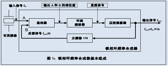
With the popularization of devices equipped with wireless communication instruments, semiconductor integrated circuit technology for wireless communication has made significant progress. Among them, the progress of phase-locked loop circuit technology is particularly prominent. The phase-locked loop circuit generates an output signal that is synchronized with the input reference signal. The basic components of this circuit are a phase detector, a loop filter, and a voltage controlled oscillator (VCO). It will correctly generate a signal synchronized with the input signal. Unlike frequency doubling circuits, phase-locked loop circuits do not directly use input signals to produce output signals. In a phase-locked loop circuit, a synchronous signal with the same frequency as the input signal is generated by a voltage controlled oscillator (VCO).


Connect a frequency divider between the output of the voltage controlled oscillator in the phase-locked loop circuit and the input of the phase detector. By synchronizing the input signal with the divided signal, the output frequency of the voltage controlled oscillator is controlled at the frequency of the division multiple. By using quartz crystal oscillators and other devices that can generate stable frequencies, and converting the frequency division of the frequency divider, the output of the voltage controlled oscillator can achieve the same accuracy as the quartz crystal oscillator and be equal to the frequency division multiple. This is the principle of frequency synthesizer.
By applying this principle, the MHz frequency band output by the AT type quartz crystal unit can be input into a phase-locked loop frequency synthesizer to generate a GHz frequency band carrier signal for wireless communication.
The use of a frequency divider is crucial when using a phase-locked loop frequency synthesizer to obtain frequencies several times higher than the input frequency. The circuit structure for obtaining N times the input frequency output is shown in Figure 1. In order to precisely set the output frequency, as shown in Figure 2, a frequency divider circuit can be set before and after the input and output of the phase-locked loop frequency synthesizer.
In order to improve the frequency setting resolution of the phase-locked loop frequency synthesizer, the frequency divider is usually directly connected after the quartz crystal oscillator unit. However, if a larger frequency division number is used to improve the frequency setting resolution, it will result in a decrease in the frequency used for phase comparison, causing slow response of the phase-locked loop, decreased loop gain, and adverse effects on the jitter and phase noise characteristics of the output waveform. To solve the above problems, a decimal frequency division phase-locked loop can also be used.
【3】 Characteristics of integer frequency division phase-locked loop and fractional frequency division phase-locked loop
The phase-locked loop circuit can be divided into two categories: integer frequency division and decimal frequency division. Both parties utilize the wave source to output high frequencies, which highlights the major features.
Integer frequency division phase-locked loop can truly generate output frequencies that are integer multiples of the input frequency. For example, when hoping to obtain a 100MHz output from a 1MHz wave source, the counter of the frequency divider is set to 100.
On the other hand, a fractional frequency division phase-locked loop can generate an output frequency that is a decimal multiple of the input frequency. This actually means that the frequency can be arbitrarily selected, that is, a small frequency setting resolution can be obtained. It can achieve a small frequency resolution, which allows for precise control of the initial frequency tolerance.
However, contrary to the above advantages, the circuit design of decimal frequency division is complex, and the integrated circuit area is larger than that of integer frequency division, so it is prone to unique distortion, resulting in poorer phase noise compared to integer frequency division. With the development of technology in recent years, the shortcomings of fractional frequency phase-locked loops have been continuously improved, and distortion has gradually decreased.
【4】 Epson's product lineup and features
The above describes the phase-locked loop circuit used to obtain high-frequency output. The biggest feature of a phase-locked loop circuit is its ability to obtain any frequency, including high frequencies, as required.
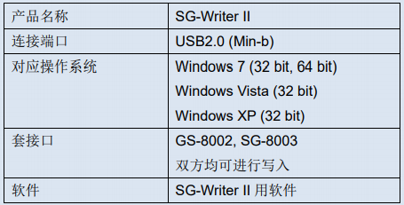
The Epson SG-8000 series adopts the integer frequency division phase-locked loop circuit introduced earlier, and provides users with an extremely rich product lineup in size and shape (Table 1). We have also prepared the SG-8000 series programming tool for users - ROM Writer (SG Writer II), for writing frequency (Table 2).
The SG-8000 series uses AT type quartz crystal units. The AT type quartz crystal unit has a temperature characteristic that follows a cubic curve and can maintain a certain degree of temperature stability. Therefore, the SG-8000 series can achieve relatively stable temperature characteristics against temperature changes without the need for temperature compensation circuits at room temperature, that is, without frequency intermittent fluctuations. All silicon MEMS oscillators with linear temperature characteristics require the use of temperature compensation circuits to maintain temperature stability, which may result in intermittent frequency fluctuations.
The high precision characteristics of these quartz crystals and the convenience of obtaining any frequency through phase-locked loop circuit technology are hoped to attract multiple customers.
Finally, it is important to note the considerations for obtaining high-frequency output through frequency doubling and phase-locked loop circuits.
Frequency doubling circuit: Attention should be paid to the mixing of subharmonics into the circuit and the jitter caused by components below n/2.
Phase Locked Loop Circuit: Attention should be paid to the loop frequency band. When connecting other phase-locked loop circuits in series after the phase-locked loop circuit, attention should be paid to jitter amplification and tracking.
Table 1: Product lineup of programmable quartz crystal oscillators

Table 2: Programming Tools for SG-8000 Series


