POP_UP_MESSAGE_CONTENT


High-Precision Real-Time Clock Modules Features of Real-Time Clock Modules with built-in digital TCXO
Preface
Whether at work or play, the concept of time is a vital part of our daily lives. From systems that dispatch trains to systems that record entry and exit times, innumerable applications depend on time data. Timing has a huge influence on profit and loss in the world's financial and stock markets. With time and clocks so essential to our everyday lives, clock functions have crept into countless everyday products in recent years. In fact, it is said that finding a product that does not have a clock of some kind is difficult. The world is also full of applications that require more accurate timekeeping, such as banking systems, security systems, and electrical power meters, to name but a few. Essential in obtaining more accurate clocks are (1) devices that oscillate at precise frequencies, and (2) ICs to control them. At Epson, we manufacture and sell modules that combine into a single package a crystal unit that oscillates at a precise, stable frequency and a real-time clock IC that controls the crystal. This article will explain the features, functions, and characteristics of Epson's high-precision, low-power real-time clock modules.
Characteristics of Epson's Real-Time Clock Modules
A real-time clock module is a single package that contains a 32.768 kHz crystal unit and a real-time clock IC, which includes oscillation circuitry clock, calendar, and alarm. At Epson, we develop and manufacture our own crystal units and real-time clock ICs, giving us a stable supply of crystal units that have been optimized for high-precision real-time clock modules and real-time clock ICs that operate under the ideal conditions for those crystal units. Epson's semiconductor technology and expertise, along with technology that enables extremely stable, low-power quartz oscillators, underlie watch control. These technologies are found at the heart of myriad timing systems and timepieces, from the official timekeeping systems used in the Olympics to luxury Seiko brand watches such as the Grand Seiko. Developing our own crystal units and real-time clock ICs enables us to design a perfect match and bring out the full potential of both. This results in products that exhibit high performance. This is what sets Epson's real-time clock modules apart from others.
The frequency accuracy of crystal units used in clock applications
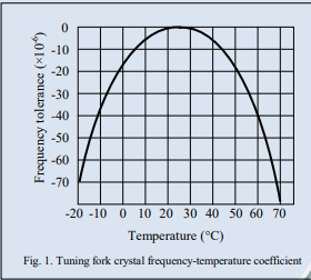
Tuning-fork crystal units are typically used in low-frequency clocks for timekeeping applications in order to meet market requirements (for example, to enable current times to be held at extremely low power consumption). While tuning-fork crystal units operate at low power, the frequency-temperature coefficient exhibits a quadratic curve, as seen in Fig. 1. Therefore, when designing the clock error, it is necessary to account for not only the frequency deviation at room temperature (+25 degrees Celsius) but also the frequency-temperature coefficient deviation of the quadratic curve.
You might think, therefore, that you would rather use an AT-cut crystal or other crystal unit that has a superior frequency-temperature coefficient as the frequency source. However, the oscillating frequency of an AT-cut crystal unit is ordinarily on the order of several MHz, so the frequency would have to be divided by an oscillation circuit to obtain the desired frequency for clock applications. The electrical current consumed by the oscillation circuit at this time would be several hundred times that consumed if a tuning-fork crystal unit were used. Therefore, we do not believe that using an AT-cut crystal unit as a clock source meets market requirements.
Frequency accuracy compensation method using a digital TCXO
The oscillation frequency of tuning-fork crystal units changes along with changes in the ambient temperature, as shown in Fig. 1 and requires a technique to compensate for these changes in order to improve clock accuracy.
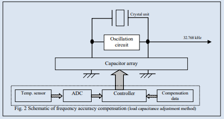
Epson uses digital TCXO temperature compensation to increase frequency accuracy. An outline of this frequency accuracy compensation method is shown in Fig. 2. In this method oscillation frequency is compensated by converting ambient temperature data to a digital value at fixed frequencies and then retrieving from memory a compensation value that is suited to that temperature. Methods for compensating oscillation frequency can broadly be divided into two types: the load capacitance adjustment method and the clock update pulse adjustment method. The load capacitance adjustment method is usually used in Epson's real-time clock modules. These two compensation methods are explained below.
Load capacitance adjustment method
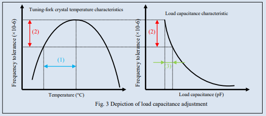
The load capacitance adjustment method corrects frequency by adjusting the crystal's oscillation frequency. The oscillation frequency of a crystal unit can be changed by increasing or decreasing the oscillation load capacitance. This method is used to correct variations in frequencies that occur in response to changes in ambient temperature. This principle is schematically depicted in Fig. 3.
The frequency-temperature coefficient of a tuning-fork crystal unit is shown on the left side of Fig. 3. The right side shows the load capacitance adjustment characteristics, wherein frequency changes according to the load capacitance value. Specifically, the frequency drift (2) is calculated from the ambient temperature data (1), and to derive the amount of change (3) in the load capacitance that corresponds to that frequency drift. The amount of the change in load capacitance corresponding to that temperature is retrieved as an offset value. The offset value is then applied to compensate the oscillation frequency. Since this method compensates the oscillation frequency directly, the oscillation frequency can be used as a low-frequency sleep clock whose oscillation output from the real-time clock module has been compensated with high precision.
Clock update pulse adjustment
The clock update pulse adjustment method compensates the frequency of the crystal unit, which is allowed to oscillate without regulation, by using part of a divider circuit to adjust the pulses. This principle is depicted schematically in Fig. 4. Specifically, the frequency drift (2) is calculated from the ambient temperature data (1), and a frequency corresponding to that frequency drift is compensated within the divider circuit and output. As shown in Fig. 4, normally if a "1 second" signal is generated on the 32,767th pulse upon the generation of a "1 second" time period on the 32,768th pulse, the 1-second cycle can be shortened. For example, if this compensation were applied every second, it would correspond to frequency compensation in the neighborhood of 30.5×10⁻⁶. By adjusting the number of pulses to generate 1 second and by changing the compensation frequency, you can significantly compensate the frequency without changing the oscillation circuit. With this compensation method, adjustments are made by a logic circuit so that 1-second signals that ultimately move the clock are accurately output. However, there is a weakness with this method: since the cycle of extracted clock signals fluctuates dynamically with the timing of temperature compensation, a CPU that uses this clock cannot run at the correct timing. For this reason, when this method is used, peripheral devices will be unable to fully benefit.
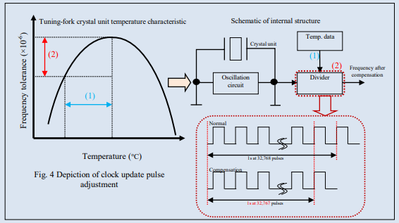
Fig. 5 shows the frequency-temperature coefficient of an Epson real-time clock module in which a digital TCXO is used to compensate frequency accuracy (the load capacitance adjustment method).
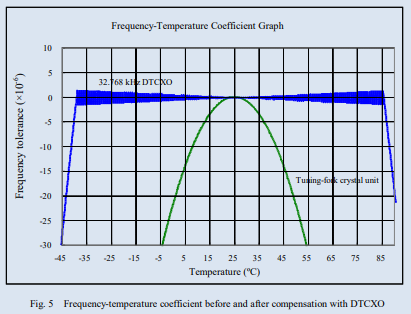
You can see from the graph that the compensated frequency of the module with the digital TCXO (blue in the graph) is extremely stable over a wide temperature range compared to the tuning-fork crystal unit (the green line in graph in Fig. 5). This demonstrates that the real-time clock module, with a monthly clock error of 9 seconds (frequency accuracy: ±3.4×10⁻⁶), has outstanding accuracy and stability.
Epson Real-Time Clock Modules with built-in digital TCXO Table 1 summarizes the characteristics of Epson's low-current real-time clock modules, all of which use a digital TCXO to guarantee outstanding frequency accuracy and stability.
Table 1. Real-Time Clock Modules with built-n digital TCXO
| Product | Interface | Backup current consumption Typ. (3V)[μA] |
Operating temperature Max |
Function (times) |
Automotive grade |
Size [mm] |
| RX8901CE | I²c | 0.24 | +105℃ | Power switching Time stamp(32) |
CE: 3.2x2.5x1.0t |
|
| RX4901CE | SPI | |||||
| RX8804CE | ²C | 0.35 | +105℃ | Time stamp(1) | ||
| RX8900CE | I²c | 0.7 | +85℃ | Power switching | ||
| RA8000CE | IC | 0.3 | +125℃ | Resetoutput Time stamp(2) |
AEC-Q100 | |
| RA4000CE | SPI | |||||
| RA8804CE | I²c | 0.35 | +105℃ | Time stamp(1) | ||
| RA8900CE | ²C | 0.7 | +85℃ | Power switching | AEC-Q200 |
Epson offer products line-up that meet customer requirements, including not only high frequency stability but also power switching functions and for automotive. As this paper explains, Epson leverages its technology for manufacturing extremely low-current tuning-fork crystal units and technology for fabricating circuits that compensate the frequency-temperature coefficient to manufacture and sell high-precision, low-power real-time clock modules. The frequency accuracy of these products is adjusted and guaranteed at the factory before shipping, so there is no need for frequency tuning by users. These products can significantly contribute to users' design-engineering efficiency and quality.


