POP_UP_MESSAGE_CONTENT


The M-G370 series of inertial measurement units are widely used in various fields of industrial systems
Basic product characteristic parameters
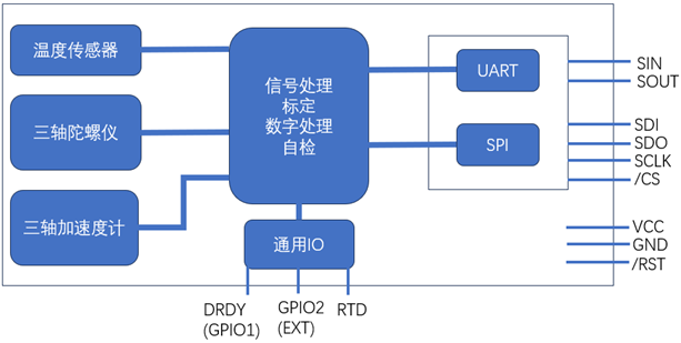
The M-G370 series inertial measurement unit adopts a single power supply of 3.3V, with a typical working current of 16mA. It can be calibrated and continuously operated in the temperature range of -40~85 ℃, with a data resolution of up to 32 bits and a data output of up to 2KSps. It supports external trigger input and external counting reset input. Among the 6 degrees of freedom, the three gyroscopes are+450 °/s, the three accelerations are+10 G, and the initial reference deviation is 360 °/h (10)/2mG (10). For more parameters, please refer to the product manual. The functional block diagram and pin diagram of the M-G370 series are shown in the following figure:

Figure 1: Functional Block Diagram
Application connection between inertial measurement unit and MCU
By simply connecting through the UART interface or SPI interface, data communication between the control system and the inertial measurement unit can be achieved, enabling system configuration, parameter calibration, and acquisition of detection results. The DRDY pin in the figure is a status output that can be connected to the interrupt input of the microcontroller. When the IMU completes a round of data detection, this pin can actively notify the MCU of the completion of the detection and send detection data to trigger the interrupt, avoiding the MCU's active query and saving the MCU's machine cycle.

Figure 2: Application Connection Block Diagram
Several application precautions:
1. Communication interface: SPI communication or UART communication can be used, but do not connect both types of communication at the same time, otherwise it may cause abnormal operation.
2. Empty pin handling: For pins that are not used in the design, they need to be connected to the VCC through pull-up resistors and should not be suspended directly
3. Reset pin: If there is no need to reset the chip in the design, this pin also needs to be connected to the VCC power terminal,
4. Input pins: All input pins in the device, There are weak pull-up resistors inside the IMU.
5. ESD protection: When storing and touching the IMU, pay attention to ESD protection, ESD may cause performance degradation, some abnormalities, or even complete damage to the device.
The M-G370 series adopts a mini design with a 20 pin plug-in interface, which facilitates installation and application according to the actual needs of the system. As shown in the following figure, the length * width * height of this IMU is 24 * 24 * 10mm, and its weight is only 10g.

Figure 3: External dimensions and markings
Based on the excellent performance parameters mentioned above, the Inertial Measurement Unit (IMU) M-G370 series can be applied in fields such as camera gimbals, navigation, vibration control and stabilization systems, and directional tracking systems.


