POP_UP_MESSAGE_CONTENT


Digital output gyroscope sensor for navigation systems
So the output changes at rest are also accumulated, which will cause significant angle errors.
Moreover, navigation systems are used in environments with drastic temperature changes, so the stability (temperature characteristics) of the output signal of the gyroscope sensor against temperature changes when stationary is also an important parameter. The digital output gyroscope sensors produced and sold by Epson combine quartz based dual T-shaped sensing components with IC chips that perform various functions to achieve high and stable temperature characteristics. IC chips can drive sensing components, amplify output signals, convert signals into digital signals through built-in AD converters, and be sensitive
Various compensations such as degree and output at rest.
This presentation explains Epson's sensing technology, temperature characteristics of digital output gyroscope sensors, and digital output interfaces.
The principle and structure of gyroscope sensors
1. Principle of Vibration Structure Gyroscope (Earth Deflection Force)
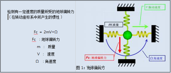
The gyroscope sensor converts the rotation of the sensor itself into an electrical signal and calculates the angular velocity. Epson applied the principle of a vibration structure gyroscope that utilizes internal vibrations of sensors. When the sensor is subjected to external rotational force, the Earth's deflection force generated in the vertical direction of the vibration part inside the sensor is utilized to generate new vibrations inside the sensor
Calculate the angular velocity through vibration.
(Earth deflection force, also known as "Coriolis force", is a physical quantity advocated by French physicist Coriolis in the 19th century, referring to the inertia that acts in a rotating coordinate system. See Figure 1.)
2. Principle (structure) of gyroscope sensor
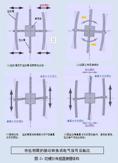
The internal vibration part of the gyroscope sensor manufactured by Epson uses quartz material and adopts a "double T-shaped structure" of parallel T-shaped quartz. The double T-shaped structure is symmetrical on both sides, such as
As shown in Figure 2, it consists of a driving arm, a detection arm, and a fixed part located in the center.
During the operation of the sensor, an alternating vibration electric field is applied to the driving arm to keep it in a state of left and right vibration, thereby offsetting leakage vibration and achieving a detection arm that remains stationary in the center (as shown in Figure 2 (1)). When one direction of the driving arm moves to the left, the other direction moves to the right, and the movement of the left and right driving arms is symmetrical, so the fixed part located in the center is not subjected to force for detection
The arm remains stationary, thus ensuring zero point stability.
Afterwards, rotational force is applied to the sensor from the outside, and the driving arm continues to swing left and right while also being affected by the Earth's deflection force, resulting in vertical vibration. Therefore, when one side of the driving arm moves upwards and the other side moves downwards, the vibration of the driving arm causes the fixed part to also receive rotational force. After the fixed part rotates under force, the detection arm that remains stationary opens
Start vibrating left and right. By converting the vibration of the detection arm into the change in charge, the angular velocity of the sensor's rotation can be detected.
3. Signal processing of gyroscope sensors (analog output signal processing of gyroscope sensors)
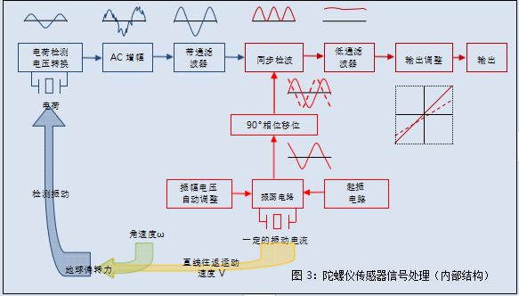
Here, we will explain the basic signal processing of gyroscope sensors (analog outputs) as an example.
① Flowing a certain current in the oscillation circuit causes the drive arm to vibrate.
② Affected by external rotational force (angular velocity) ω ) Afterwards, the Earth's deflection force is generated to detect the vibration of the detection arm.
③ After amplifying the detected signal, perform waveform compensation.
④ Compare the vibration waveform of the driving arm after a 90 degree phase shift with the vibration waveform of the detection arm, and calculate the angular velocity.
In the vibration detection of the arm, the phase of the output signal is different when the rotation angle is -30 degrees (30 degrees to the left) and when the rotation angle is 30 degrees (30 degrees to the right). Therefore, the
By comparing the output waveform with the waveform of the driving vibration, the correct angular velocity and rotation direction can be determined.
⑤ Adjust the output to output the voltage corresponding to the angular velocity.
As mentioned above, the analog output gyroscope sensor separates the Earth deflection force signal from the weak detection signal and amplifies it to output a voltage proportional to the angular velocity.
[Function and characteristics of digital output gyroscope sensor]
Figure 4 shows the block diagram of the XV4001 series digital output gyroscope sensor. The following illustrates its functions and the two digital output interfaces it corresponds to (three wire, four wire SPI, and I2C).
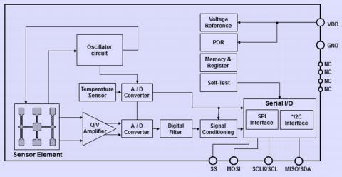
Figure 4: Block diagram of XV4001 series digital output gyroscope sensor
function
·Angular velocity output: Output angular velocity data in the form of a 16 bit, 2 complement.
·Digital filter: A digital low-pass filter with built-in fc=10Hz.
·Temperature sensor: Output temperature data in the form of a complement of 11 bits and 2.
·Power on reset (POR): Built in power on reset circuit that outputs the power on reset signal required for the initialization of the logic circuit when starting the power supply.
·Self detection: Built in self detection circuit, transmitting self detection results through communication response (DIAG).
Digital output interface
·SPI (Four wire, Three wire)
It can handle communication frequencies up to 10MHz and is equipped with command error detection and checksum functions to ensure communication quality. Moreover, the gyroscope sensor itself also has the ability to detect
The self detection function for detecting anomalies will attach the judgment results to the output frame of the angular velocity or temperature sensor and send them. Based on the judgment results, it can be determined whether the sensor is abnormal.
·I2C
Dealing with fast mode up to 400kbit/s. Set the slave address to 1101000 and the sub address to 1101001 (the sub address is set when the factory products are shipped). Can be achieved through
The output command of self detection judgment result issued is used to determine the result of self detection.
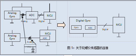
Figure 5 shows an example of the connection between the gyroscope sensor and the microcomputer.
In the past, when analog output gyroscope sensors collected signals through AD converters, it was necessary to insert the required filter circuit between the gyroscope sensor and the AD converter to prevent aliasing (folding distortion). The XV4001 series described in this case adopts a digital output interface, so the signal output from the gyroscope sensor can be directly transmitted to processors such as microcomputers without the need for an AD converter. It can also be connected via bus, connecting multiple devices on the same signal line, which is more convenient compared to the original analog output gyroscope sensor In terms of wiring.
Characteristics (temperature characteristics) of the XV4001 series gyroscope sensor
Users naturally hope that the output of the gyroscope sensor remains unchanged when it is not rotating (stationary). Especially for navigation systems, as the angular velocity output from the gyroscope sensor will be integrated, the variation in angular velocity output will have a significant impact on position accuracy calculation. There are many factors that cause the deviation of angular velocity output, among which temperature changes cause
The impact is most significant. Figure 6 shows the temperature characteristics of the output of a gyroscope sensor without temperature compensation in a stationary state.
The gyroscope sensors produced by Epson use sensor components made of quartz material. Therefore, it can be seen that the angular velocity output changes very little without temperature compensation.
But it also indicates that there are differences in the slope and variation of temperature characteristics for each product.
In the navigation system, it can be used after compensating for the angular velocity output temperature characteristics of the gyroscope sensor in the processing system. However, from the perspective of both technology and cost, this method is difficult to compensate for the temperature deviation in the direction and quantity of temperature characteristics of each product within the entire working temperature range. Therefore, users are increasingly demanding gyroscope sensing
The device itself has high and stable angular velocity output temperature characteristics. Epson responded to market demand by using digital compensation circuits to perform high-order temperature compensation on the output at rest.
Figure 7 shows the temperature characteristics of the Epson gyroscope sensor output when stationary, after temperature compensation using a digital compensation circuit.
Epson's gyroscope sensor, after undergoing high-order temperature compensation, significantly improves the dispersion and achieves a stationary angle under a wide range of temperature conditions from -40 ℃ to+85 ℃
The speed output maintains a stable temperature characteristic.

Characteristics of XV4001 series gyroscope sensor (temperature characteristics)
Users naturally want the output of the gyroscope sensor to remain unchanged when not rotating (stationary). Especially for navigation systems, as the angular velocity output of the gyroscope sensor will be integrated, changes in angular velocity output will have a significant impact on position accuracy calculation. There are many factors that can cause deviation in angular velocity output, among which temperature changes can cause
The impact is most significant. Figure 6 shows the temperature characteristics of the gyroscope sensor output without temperature compensation in a stationary state.
The gyroscope sensors produced by Epson Company use sensor components made of quartz material. Therefore, it can be seen that without temperature compensation, the change in angular velocity output is very small.
But this also indicates that there are differences in the slope and variation of temperature characteristics for each product.
In the navigation system, it can be used to compensate for the angular velocity output temperature characteristics of the gyroscope sensor in the processing system. However, from a technical and cost perspective, this method is difficult to compensate for temperature deviations in the direction and quantity of temperature characteristics for each product throughout the entire operating temperature range. Therefore, users have increasingly high requirements for gyroscope sensing
The device itself has high and stable angular velocity output temperature characteristics. Epson responds to market demand by using digital compensation circuits to perform high-order temperature compensation on stationary outputs.
Figure 7 shows the temperature characteristics of the Epson gyroscope sensor output at rest after using a digital compensation circuit for temperature compensation.
Epson's gyroscope sensor, after high-order temperature compensation, significantly improves dispersion and achieves a fixed angle under wide temperature conditions from -40 ℃ to+85 ℃
The speed output maintains a stable temperature characteristic.
Table 1: Overview of XV4001 series


