POP_UP_MESSAGE_CONTENT


Epson M-G365 / M-G366 MEMS six-axis gyroscope replaces fiber optic gyroscope
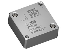
Epson M-G365 / M-G366 is a high performance measuring device with optical fiber instrument (FOG) performance. As a new generation IMU standard, it is simple to install, has new attitude angle output function and support various applications, and high speed DSP with extended Kalman filter can provide high precision real-time attitude angle output (roll / pitch / yaw) with low power consumption, which can be widely used in vehicles, ships and other industrial products and systems. It is used to measure the data and control the movement, and the system end no longer needs the high-speed calculation of the dynamic attitude Angle, thus reducing the system load and power consumption. The M-G365 uses the newly developed high-performance sensor, which has superior stability, lower noise, wider dynamic range, and excellent dynamic performance (scale factor nonlinear), which is ideal for high-precision measurements such as cars and unmanned aircraft from static to high-speed motion. The backward compatibility of M-G365 greatly reduces the user development cost and evaluation time, and has a lower current consumption (16 mA, compared with 18 mA for M-G364 and M-G354)

Assessment and test environment construction:

Figure 1. Block diagram of the environment construction
The above interface split board is used to connect the 1mm pitch connector of the Epson M-G365 6-axis MEMS gyroscope (inertial measuring device) to the 2.54mm pitch connector. With the USB-serial adapter, the PC can control the inertial measurement device, greatly simplifying the test and evaluation of the product.
Description of the six-axis gyroscope terms:
* 1 Inertial measuring device (IMU) is a device used for sensing inertial motion. It has a three-axis angular velocity sensor and a three-axis accelerometer. Also known as a six-axis gyroscope, it belongs to the MEMS gyroscope.
* 2 Fiber optic gyroscope (FOG) is a gyro sensor based on fiber optic and optical interference properties used in a small number of high-performance IMUs.
* 3 The gyro sensor (angular velocity sensor) measures the rotation angle of an object about the reference axis per unit time (angular velocity).
* 4 Zero-bias stability is an indicator of the stochastic variation of the gyroscope calculated over the prescribed sampling time and the mean time interval, which is expressed by the 1 / f noise density.
* 5 The angular random walk is an indicator of the zero-biased stochastic change of a gyroscope calculated over the prescribed sampling time and the mean time interval, expressed by a random noise density.
* 6 The extended Kalman filter calculates the most likely values using the model valuation and the actual observed values successively, in order to more accurately predict the information in the observed values, including the filter error.
* 7 Digital signal processor (DSP) is a high-speed computing circuit that processes digital signals.
* 8 Azimuth (roll, pitch and yaw):
Roll angle: the angle at which the object rotates along its longitudinal axis
Pitch angle: the angle at which the object rotates along its horizontal axis
Yaw angle: the angle at which the object rotates along its vertical axis
The fiber-optic gyroscope (FOG), formerly a low-cost alternative to other technologies such as the ring laser gyroscope (RLG), now faces new competition from the self-Epson high-precision six-axis gyroscope. Microelectromechanical systems (MEMS) gyroscopes are starting to grab market share for traditional FOG applications. Specifically, antenna array stability, agricultural machinery control, and conventional vehicle navigation have become the battleground for the confrontation between MEMS and FOG.
Epson MEM six-axis gyroscope is very close to FOG fiber gyroscope in terms of performance parameters, especially EPSON's latest M-G365 series parameters have reached the FOG tactical performance level, but its cost is several times lower than MEMS. If the GNSS can be used and the application is intended to operate in an open sky environment, the MEMS six-axis gyroscope can replace the OG ray gyroscope. If the application can receive vehicle or platform speed updates, the Epson MEMS six-axis gyroscope system can reach the same level as the independent FOG system. This will quickly accelerate the spread of six-axis gyroscopes in areas such as autonomous driving vehicles.
For ordinary vehicle navigation, this will not have an impact, but the system is designed for applications that need to adapt to high rate control. In addition, several MEMS gyroscopes provide good bias stability, but with reduced bandwidth or high noise. The MEMS gyroscope chosen for this system achieves a balance between bandwidth and performance. The above table gives the actual specifications of the selected MEMS.
The MEMS gyroscope used by the M-G3656-axis gyroscope uses a multi-core architecture that achieves an optimized balance between stability, noise, linearity, and linear g performance. The complete differential four-resonator is closely coordinated with the in-chip high-performance signal conditioning, so that the resonator has the minimum necessary response range, is located in the highly linear zone, and provides a high degree of vibration suppression.
Since the MEMS gyroscope and accelerometer are integrated into the multiaxis IMU (see Figure 1), the x / y / z orthogonality of the sensor may be the primary source of error. The main error sources are often specified by the cross-axis sensitivity or alignment error. The common specification is the ± 2% cross-axis sensitivity. The IMU of this system has a 0.087% span sensitivity (0.05° orthogonality). More importantly, this specification is valid in the temperature range because the device-specific calibration is completed before leaving the factory.


