POP_UP_MESSAGE_CONTENT


Detailed Introduction to Surface Acoustic Wave (SAW) Filter and Bulk Acoustic Wave (BAW) Filter
Filters can be divided into LC filters, cavity filters, acoustic filters, dielectric filters, etc. based on their implementation methods. Different filters are suitable for different application scenarios. In mobile wireless communication applications, due to the small size and low power of the device, smartphones currently use small volume and high-performance acoustic filters, which can be divided into Surface Acoustic Wave (SAW) filters and Body Acoustic Wave (BAW) filters according to their different structures. The basic principle of SAW filters is to convert wireless signals into acoustic signals at the input end through piezoelectric effects and propagate them on the surface of the medium. At the output end, the acoustic signals are converted into wireless signals through inverse piezoelectric effects. A basic SAW filter consists of piezoelectric materials and two interdigital transducers (IDTs). The input IDT converts electrical signals into sound waves, which propagate laterally in the form of standing waves on the surface of the SAW filter substrate. The output IDT converts the received sound waves into electrical signals for filtering. SAW products include ordinary SAW filters and TC-SAW filters with temperature compensation characteristics. The product forms include duplexers and individual filters. The main raw materials for production are single crystal wafers of lithium tantalate or lithium niobate (mainly 4-inch wafers). Semiconductor processes such as photolithography and coating are applied above the wafers for graphic processing, and then cut into chips. The surface structure and manufacturing process of the chips are relatively simple, and the cost is relatively low.
Common acoustic filters include SAW, BAW, FBAR, and XBAR
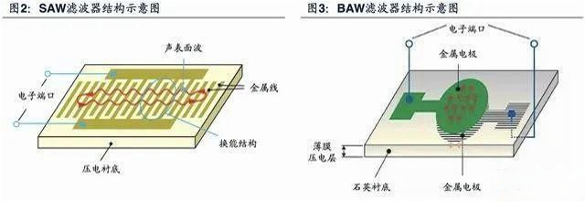
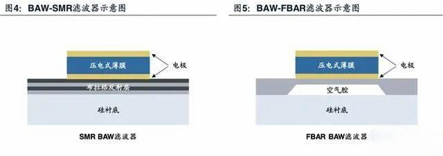
The basic principle of BAW filters is the same as SAW filters, but the difference is that sound waves propagate vertically in BAW filters. At the same time, the use of electrodes and the thickness of the thin film piezoelectric layer determine the resonant frequency of the filter. At high frequencies, the thickness of the thin film piezoelectric layer is in the order of a few micrometers, so it is necessary to use more difficult thin film deposition and micromachining techniques, which makes manufacturing more difficult and costly. Tuoti Electronics/Silvoc believes that BAW filters have FBAR and SMR types, with slight differences in their structures. BAW filters can be directly processed and designed on silicon wafers (mainly 6 inches), and the key process is to use PVD or CVD equipment to prepare piezoelectric thin films. The thin film materials are mainly aluminum nitride and zinc oxide.
SAW filter is the abbreviation of surface acoustic wave filter. It is a filtering device made of piezoelectric materials such as quartz crystals and piezoelectric ceramics, utilizing their piezoelectric effect and physical characteristics of surface acoustic wave propagation. It is widely used in intermediate frequency circuits of televisions and video recorders to replace LC intermediate frequency filters, greatly improving the quality of images and sound. Tuoti Electronics/Silvoc reminds you that Surface Acoustic Wave (SAW) is an elastic wave generated and propagated on the surface of a piezoelectric substrate material, and its amplitude rapidly decreases with increasing depth of penetration into the substrate material.
Schematic diagram of SAW filter principle:
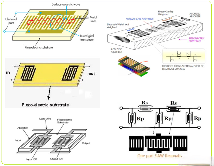
The structure of the SAW filter is shown in the figure. It is composed of a substrate made of piezoelectric materials and a comb shaped electrode fired on top of it. After inputting a signal to the surface acoustic wave filter, mechanical vibration waves with the same frequency as the applied signal will be generated on the surface of the electrode piezoelectric material. The vibration wave propagates at the speed of sound waves on the surface of the piezoelectric substrate. When the wave reaches the output end, a transducer composed of comb shaped electrodes at the output end converts the sound energy into a transformer signal output.
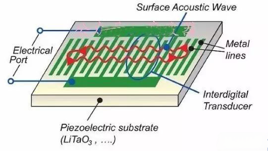
It is not difficult to see from the above introduction that the SAW filter is composed of two transducers. The input transducer converts electrical energy into sound energy and emits surface acoustic waves, while the output transducer converts the received surface acoustic wave sound energy into electrical energy output. The surface acoustic wave filter utilizes these two transducers on a piezoelectric substrate to generate and detect surface acoustic waves, in order to complete the filtering function.
The main characteristics of SAW filters are: high design flexibility, analog/digital compatibility, excellent group delay time deviation and frequency selectivity (optional frequency range of 10MHz~3GHz), small input and output impedance error, low transmission loss, good electromagnetic interference (EMI) resistance performance, high reliability, small device size, light weight (its volume and weight are about 1/40 and 1/30 of ceramic dielectric filters, respectively), and the ability to achieve various complex functions.
BAW - Body Acoustic Wave Filter
Although SAW and TC-SAW filters are very suitable for applications up to approximately 1.5GHz, BAW filters have significant performance advantages above 1.5GHz (Figure 2). The size of the BAW filter also decreases with increasing frequency, making it very suitable for demanding 3G and 4G applications. In addition, even in high bandwidth designs, BAW is not as sensitive to temperature changes, and it also has extremely low losses and very steep filter skirts.
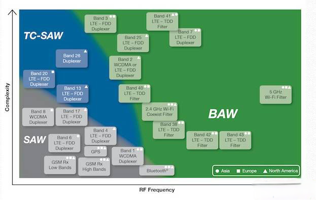
Figure 2: BAW filters have significant performance advantages above 1.5GHz
Unlike SAW filters, sound waves propagate vertically within BAW filters. For BAW resonators using quartz crystals as substrates, the metal embedded on both sides of the top and bottom of the quartz substrate excites the sound waves, causing them to bounce back from the top surface to the bottom to form standing sound waves. The thickness of the slab and the mass of the electrode determine the resonance frequency. At high frequencies where BAW filters excel, the thickness of the piezoelectric layer must be in the order of a few micrometers. Therefore, thin film deposition and micromachining techniques must be used on the carrier substrate to achieve a resonator structure.
Because both types of BAW filters have high sound energy density and their structures can effectively guide and limit sound waves, their losses are very low. At microwave frequencies, BAW can achieve higher Q values, comparable volumes, and any other type of filter, achieving: 2500@2GHz . This allows for excellent suppression and insertion loss performance even at tight edges of the passband.
Although the manufacturing cost of BAW and FBAR filters is higher, their performance advantages are very suitable for the challenging LTE and PCS frequency bands, with only a narrow transition range of 20MHz between the sending and receiving paths of the latter. Tuoti Electronics/Silvoc believes that the IDT of BAW and FBAR filters can be made large enough to support 4W@2GHz Higher RF power. BAW devices have inherent high impedance to electrostatic discharge, and their BAW-SMR variant has a TCF of approximately -17ppm/℃ @ 2GHz.
With the trend of spectrum congestion leading to narrowing or even abandoning the protected frequency band, the demand for high-performance filters has significantly increased. BAW technology makes it possible to design narrowband filters with very steep filter skirts, high suppression performance, and small temperature drift. It is very suitable for dealing with very tricky interference suppression problems between adjacent frequency bands. Engineers from TAISAW (TST: Jiashuo Technology) and other filter manufacturers are working hard to achieve BAW-SMR filters with 4% or higher bandwidth, lower losses, and almost zero TCF.
The manufacturing process steps required for BAW devices are 10 times that of SAW, but because they are manufactured on larger wafers, each wafer produces about 4 times more BAW devices. Nevertheless, the cost of BAW is still higher than that of SAW. However, for some challenging frequency bands assigned above 2GHz, BAW is a * * * available solution. Therefore, the share of BAW filters in 3G/4G smartphones is rapidly increasing.
The acoustic reflector used below the bottom electrode of the BAW-SMR filter provides optimized bandwidth performance in challenging frequency bands for FBAR. The use of silica in the reflector also significantly reduces the overall temperature drift of BAW, which is much better than the level that BAW and even FBAR can achieve. Due to the resonator being located on a sturdy material block, its heat dissipation is much better than FBAR, which uses a membrane and can only dissipate heat through the edges. This enables BAW devices to achieve higher power density, and soon there will be 10W level devices available for small cellular base station applications.


