POP_UP_MESSAGE_CONTENT


Performance of Quartz Crystals and MEMS Oscillators
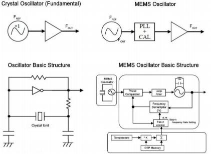
EPSON tested and measured quartz oscillators and mems oscillators, and compared six parameters that are crucial for the design of communication, networking, industrial, and consumer electronics devices. EPSON also provides a summary of compiled data:
1) Power consumption: How much current is consumed?
2) Oscillator start: The speed at which the oscillator starts after being powered on.
3) Jitter and phase noise: What is noise performance (a key factor in communication equipment)?
4) Frequency vs. Temperature characteristics: How stable is the frequency relative to temperature changes?
5) Frequency stability: How stable is the frequency measured at 25 ° C?
6) Vibration sensitivity: performance under adverse conditions
7) Reliability: Mean time between failures. Also known as (MTBF)
8) Summary: Overall performance evaluation.
1) Power consumption
Quartz based oscillators have lower power consumption due to their advantages of a fundamental frequency oscillation or harmonic oscillation and a simple circuit structure.
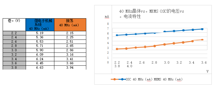
In contrast, MEMS based oscillators consume more power because they have more circuits. PLL and LCVCO have increased total power consumption. Therefore, MEMS oscillators require 6.09 mA, while standard quartz oscillators require approximately 3.16 mA, which is twice the current required for MEMS and can only achieve similar jitter and phase noise levels for quartz oscillators.
Figure 2: Power consumption measurements of MEMS and quartz oscillator at 40MHz.
2) Starting characteristics of oscillators
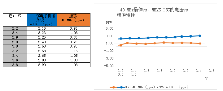
Compared to the stability of the oscillator when powered on, the quartz oscillator achieves power on accuracy almost at 1 ppm. The MEMS oscillator is striving to achieve an accuracy of 2 ppm. After startup, the quartz oscillator is stable, but as you can see, the MEMS oscillator exhibits frequency oscillations. As shown in Figure 3 below.
Nowadays, rapid entrepreneurship is more important than ever before. Whether it's consumer products, automation products, or military products
Applications, today's electronic products need to be turned off and on to increase battery life or bring the system online. The clock should start stable operation when needed. Using a faster start-up and stabilization speed oscillator, such as a quartz oscillator from EPSON, allows for shorter wake-up cycles and longer battery life.
Figure 3: Oscillator startup characteristics at 40 MHz
3) Jitter and phase noise
A) Ejector
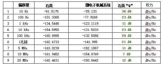
We have chosen a ready-made and reasonably priced oscillator. One has a MEMS based resonator, and the other is a quartz based resonator. When measuring the jitter of MEMS oscillators from 12 kHz to 20 MHz, we obtained a jitter of 1.5 pS rms. When testing a quartz crystal oscillator between 12 kHz and 20 MHz, we achieved a root mean square jitter of 0.18 pS. This is almost 8 times the size of a MEMS oscillator. Choose the EPSON section for comparison, as it is a "standard oscillator" used in many applications and in mass production. See Figure 4 below.
B) Phase noise
Laboratory measurements also indicate that quartz oscillators have better phase noise than MEMS oscillators.
MEMS oscillators have high phase noise due to poor Q or quality of silicon resonators. At 10 Hz, the quartz oscillator has a phase noise of 36 dB compared to the MEMS oscillator. The phase noise at low offset is crucial for wireless communication and may lead to some errors in optical communication.
MEMS oscillators also have higher phase noise for high offsets (12 kHz to 20 MHz), as they use a low q LC oscillator in PLL circuits.
Figure 4: Phase noise performance of quartz. Microelectromechanical systems
MEMS oscillators have thermal spikes caused by fractional n dividers. These hot spikes occur within the band and cause deterministic jitter (DJ), which can reduce system error performance. Stimulus induced DJ must be considered as part of the jitter budget for all types of circuits: wired, optical, and wireless. A quartz oscillator using basic crystals does not have such spikes.
Figure 5: Comparing the jitter and phase noise of oscillators.

4) Frequency stability
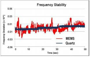
The measured values of frequency stability for each oscillator are shown in Figure 6. These results were measured at 3.3 V and 25 ° C for 50 seconds. The frequency jump of MEMS is around ± 600 ppb, far exceeding most wireless standards. The movement ability of quartz based oscillators is small and more stable.
Figure 6: Stability diagram of quartz oscillator and MEMS oscillator
5) Frequency over temperature characteristics
When comparing frequencies. Temperature stability of quartz and MEMS. You can see that the quartz based oscillator follows the continuous cubic curve of AT crystals, reaching ± 25 ppm from -40 ° C to+85 ° C, which is good enough for most applications.
From the MEMS graph, it seems to have better frequency and temperature characteristics, but if you look closely, you can see that the graph shows the frequency jump caused by adjusting the PLL division ratio to compensate for temperature changes. This leads to significant frequency jumps to compensate for significant frequency drift of MEMS resonators (30ppm/° C or 3750ppm 40 ° C~+85 ° C). Quartz is more stable in temperature than MEMS and provides higher "Q" performance. Shi Yingji
The oscillator does not require temperature compensation to maintain stability as low as ± 10 ppm within the required temperature range. If better stability is needed, you can add a temperature compensated oscillator to quartz with stability as low as 0.5 ppm.

MEMS technology also claims to have other improvements over quartz technology, but when you look closely at these areas, you find that giving up is more than what you get. In this world, nothing is free.
6) Vibration sensitivity
MEMS claims to have improved performance in vibration sensitivity. If we take a look at these data, this will soon be exposed. typical
The measurement range ranges from less than one level to 2 kHz. The vibration density level is significantly reduced by more than 2 kHz. We measured the phase jitter integral in the range of 12 kHz to 20 MHz. This range is significantly higher than the maximum vibration level that any customer would specify. With the improvement of quartz geometry, higher frequency blanks, and better manufacturing processes, quartz manufacturers have greatly increased their vibration sensitivity to MEMS.
The measurement unit for vibration sensitivity is one billionth of a gram of vibration (ppb/g)
A) The vibration sensitivity range of MEMS is 0.01 ppb/g~1 ppb/g.
B) The sensitivity range of quartz vibration is 0.1 ppb/g~1 ppb/g


