POP_UP_MESSAGE_CONTENT


New knowledge of low-frequency oscillation circuits
catalogue
1. Market trends in electronic device products
2. Trends in tuning fork crystal units and semiconductor process technology
3. The impact of miniaturization on characteristics and its countermeasures
3-1. The decrease in oscillation stability caused by an increase in CI value (Crystal Impedance)
3-2. Deviation of oscillation frequency
3-3. Oscillation faults caused by low voltage of microcomputers (MPUs) 3-4 crystal oscillator
4. Introduction to Epson Toyocom's overall solution for the kHz frequency band
4-1. Tuning fork type crystal unit
(1) Product lineup of tuning fork crystal units
4-2. 32.768 kHz oscillator
(1) 32.768 kHz crystal oscillator product lineup
1. Market trends in electronic device products
In recent years, with the increasing awareness of reducing environmental loads, there has been an increasing market demand for electronic device products that can maintain high performance, reduce raw materials through miniaturization of equipment and instruments, and completely reduce power consumption. The market changes for electronic components are also similar, and crystal components used as reference clocks also require small size, low power consumption, high precision, and high reliability. This is not simply a problem of reducing the size of the parts. Reducing the size means the emergence of new issues and making the original issues more prominent.

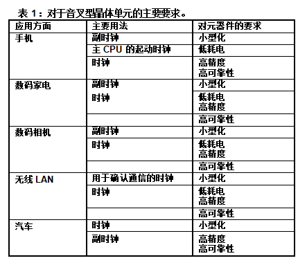
Table 1 summarizes the main requirements for crystal units (tuning fork type crystal units) in the kHz frequency range for each major application. As shown in the table, the tuning fork type crystal unit is mainly used for machine clocks, microcomputer secondary clocks, and timing. As a necessary component, it is widely used in various applications. From the table, it can be seen that there is a growing trend in the demand for small size, low power consumption, high precision, and high reliability in any market.
2. Trends in tuning fork crystal units and semiconductor process technology
Figure 1 shows the trend of size variation of tuning fork crystal units. From the past 20 years, it can be seen that the volume has decreased from about 150 mm3 to about 1.5 mm3, sharply dropping to the initial 1/100, and miniaturization is constantly progressing. We believe that research and development will also move towards miniaturization in the future.
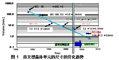
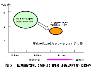
Figure 2 shows the trend of fine-grained design rules for low-power microcomputers (MPUs) with built-in oscillation circuits.
The previous design rules were 0.2 μ m to 0.3 μ m, and power supply voltage VDD=1.8 V to 3.0 V was usually used for driving. But in recent years
With the progress of refinement and low voltage, it has jumped into the field of 0.1 μ m~0.15 μ m and VDD=1.5 V~1.8 V drive.
In addition, the power consumption requirement level during standby has also decreased from around 0.3 μ W in the past to 0.1-0.2 μ W in recent years. We believe that the refinement of design rules to reduce costs and the low-voltage driving caused by power consumption reduction are the expected trends of the times that will not stop.
Due to the changing trends in tuning fork crystal units and semiconductor production technology mentioned above, our technical support team has received numerous failure cases as shown below:
·The deterioration of oscillation stability is caused by the increase in CI value of the tuning fork type crystal oscillation unit.
·The increase in frequency sensitivity of the tuning fork type crystal oscillation unit causes a shift in the oscillation frequency.
·Due to the refinement and low voltage of semiconductor design rules, the performance against power source noise is reduced or the oscillation allowance is insufficient, making it impossible to obtain stable oscillations.
In the next chapter, we will explain the unique points of attention for these tuning fork crystal units that are accompanied by miniaturization and low voltage.
3. The impact of miniaturization on characteristics and its countermeasures
3-1. The decrease in oscillation stability caused by an increase in CI value (Crystal Impedance)
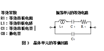
If the resonant state of the crystal unit is replaced by an electrical circuit, the equivalent circuit of the crystal oscillation unit shown in Figure 3 can be obtained, with a CI value equivalent to R1 of the equivalent circuit. When the crystal oscillation unit is usually miniaturized, the CI value will increase. At this point, the impact of the CI value of the crystal oscillation unit on the oscillation circuit and its countermeasures are shown below.
[Impact]
When the CI value is large, the starting or stopping voltage will increase. Even if the voltage is increased, it will be difficult to start oscillation, and a slight decrease in voltage will make oscillation unstable or stop oscillating.
Moreover, the CI value is the equivalent impedance of the resonant frequency in the crystal oscillator unit, which is one of the important parameters that affects the instability or non oscillation of the oscillation and determines the oscillation margin.

Countermeasures
Firstly, it is necessary to ensure that the oscillation margin of the scale used to measure whether the oscillation circuit can oscillate stably is above 5-10. This oscillation margin can be expressed by dividing the negative impedance (CI) of the oscillation circuit in Figure 4 by the maximum equivalent series impedance (r) of the crystal oscillation unit.
When the oscillation margin is insufficient, faults such as delayed onset time or increased onset voltage will occur as described above. Moreover, when the oscillation margin is significantly insufficient, the oscillation will fall into an unstable or non oscillating state.
To improve oscillation margin, the following two methods are more effective:
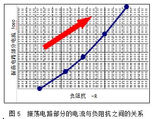
① The method of improving negative impedance is usually more effective. According to the relationship between the power consumption of the oscillation circuit and negative impedance shown in Figure 5, the method of increasing the current of the oscillation part can be used to solve it. However, this method has the disadvantage of increasing power consumption.
② The use of quartz crystals with lower CI values can also improve the oscillation margin, but as mentioned above, the miniaturization of crystal oscillation units usually leads to an increase in CI values.
Although miniaturization and stable oscillation are opposite, our company uses QMEMS technology and adopts a design that is both small and can suppress CI values. Our company has launched a lineup of crystal oscillation units with diverse specifications and sizes according to customer needs, which can provide you with the best components of the system and support the high design quality of esteemed customers.
3-2. Deviation of oscillation frequency
As the size of the oscillator becomes smaller, frequency sensitivity will increase. When installed on the product substrate, the oscillation frequency may deviate from the expected value. The following is an explanation of its impact and countermeasures.
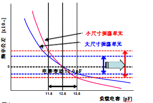
Figure 6 Capacitance characteristics
[Impact]
The frequency of the crystal oscillation unit varies with the load capacitance of the oscillation circuit. This change is called "frequency and load capacitance characteristics". The load capacitance, as shown in equation 1), is determined by the capacitance value and stray capacitance of the oscillating circuit.
The frequency and load capacitance characteristics are shown in Figure 6, which vary with the size of the oscillator. The frequency accuracy increases with the miniaturization of the oscillator size, and the frequency sensitivity of the capacitor capacity per 1pF increases (the curve tilt becomes sharp). Therefore, the frequency is easily affected by the uneven stray capacity of each substrate. The deviation of oscillation frequency increases.
The countermeasures for the crystal oscillation circuit in this situation are as follows.
Equation 1) CL ≈ Cg x Cd/(Cg+Cd)+Cs (Cs: stray capacity of the circuit)
Countermeasures
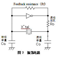
Figure 7 shows a typical crystal oscillator circuit using CMOS ICs.
By changing the gate capacity CG and drain capacity CD in this figure, the oscillation frequency can be adjusted. Therefore, the following methods can be adopted:
① Choose capacitors with smaller unevenness in CG and CD;
② Select crystal oscillation units with low sensitivity.
By using the above viewpoint to select components, stable frequency accuracy can be achieved.
Our company's products use "QMEMS" technology and adopt a design that is both small and can suppress sensitivity and uneven distribution of each product.
Using such products is also one of the effective means.
3-3. Oscillation faults caused by low voltage of microcomputers (MPUs)
(1) The changing trend of low power consumption microcomputer (MPU) development
The miniaturization, low power consumption, and multifunctionality at the end of the product are constantly advancing, and the requirements for MPUs widely used for various purposes are also the same. In response to these requirements, MPU's product development focuses on the following aspects:
·The reduction in the number of semiconductor chips and the implementation of single-chip technology;
·The refinement of the design rules adopted (refer to Figure 2)· Low voltage, low power consumption.
(2) Low power consumption of 32.768kHz oscillation circuit
In contrast to this development process, various constraints have also been imposed on the 32.768kHz oscillation circuit. Especially the 32.768kHz clock is always in operation within the MPU, making it considered the most important feature to achieve low power consumption.
Among them, as sensor networks and ecological products that will attract attention in future application fields, they need to work for a long time under battery power, so this trend is more significant.
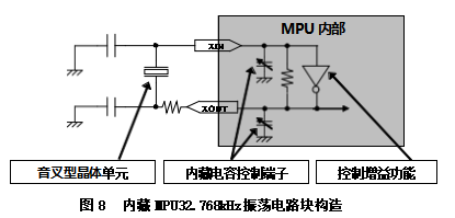
Recently, in order to achieve low power consumption of 32.768kHz clocks, various semiconductor manufacturers have adopted the following methods for 32.768kHz oscillation circuits
The various techniques shown. Figure 8 is one of the construction examples of oscillation circuit blocks, with different specifications from semiconductor manufacturers.
Using variable inverted amplifiers (with variable voltage gain and variable number of internal inverted amplifiers)
Using variable internal capacitance
Adopting a program to reduce the direct current when the inverter amplifier is turned on
[Impact]
Due to the above two changing trends, low power consumption is constantly progressing, but the negative impact is easily affected by the following: · weaker noise;
·Inaccurate oscillation frequency;
·Unable to ensure oscillation margin.
In order to achieve low power consumption and stable oscillation, it will become increasingly important to properly evaluate semiconductor, substrate, and crystal oscillation units.
Countermeasures
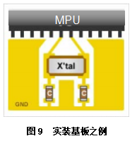
It is important to conduct oscillation circuit evaluation tests using the actual semiconductors, circuit substrates, and crystal oscillation units used in the product design stage. The oscillation circuit evaluation test may require the crystal oscillation unit manufacturer to carry out. Firstly, substrate design will become a focus. When designing the substrate, please note the following: (refer to Figure 9)
① The oscillation circuit (oscillation unit, oscillation capacitor) should be configured near the oscillation IC (MPU, etc.);
② The substrate wiring should be the shortest and not cross (within 20 mm);
③ Configure GND on the lower substrate of the crystal oscillation unit;
④ When using multi-layer substrates, no other signal lines are configured in the lower inner layer of the crystal oscillation unit.
If the above issues are not taken into consideration in the design, it will cause various faults such as non oscillation, unstable oscillation, and inaccurate frequency. Please be careful.
Epson Toyocom is working with semiconductor manufacturers to promote reference activities, and the following key points have been posted on our company's website: · The composition of semiconductor circuits;
·We recommend crystal oscillation units that match semiconductors· Precautions when designing substrates.
We plan to gradually increase the number of target semiconductors. For details, please refer to
http://www.epsontoyocom.co.jp/english/tech/circuitdesign.html .
3-4. crystal oscillator
Unlike the previous strategy, using a crystal oscillator in the design is also a very effective strategy. Crystal oscillator is a product that integrates crystal oscillation unit and oscillation circuit, and has the following advantages:
The built-in oscillation circuit ensures that the oscillation action, frequency accuracy, oscillation waveform, and other characteristics are in the optimal state for use; There is no need to change the circuit constant of the oscillating capacitor, nor is there a need for circuit evaluation of the entire substrate;
The conflicting requirements of stable oscillation and low energy consumption operation have been adjusted and matched to achieve the highest balance.
Due to these characteristics, the design workload and design risks of low-frequency oscillation circuits, which are constantly increasing in difficulty, can be greatly reduced.
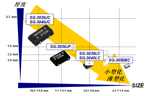
Moreover, Epson Toyocom not only integrates the crystal oscillation unit with the oscillation circuit, but also develops a small-sized SG-3050BC with a size of 2.2 × 1.4 × 1.0t mm. Small in size and only requiring power connection to perform its functions, it can contribute to improving the freedom of the practical installation area.
The above products can provide both small and superior oscillation characteristics simultaneously.
Epson Toyocom's Progress
As mentioned in this chapter, with the progress of miniaturization of crystal oscillation units, performance such as CI value, uneven characteristics, and frequency sensitivity have deteriorated, making circuit design more difficult. Epson Toyocom utilizes the core technology known as "QMEMS" to design and produce tuning fork crystal oscillators that can simultaneously achieve both small and high-performance applications, contributing to the development of small and high-performance applications.
When producing tuning fork crystal oscillation units, we did not use the commonly used mechanical processing methods in production. Instead, we used QMEMS technology evolved from photolithography with a 30 year history and practical achievements. Through three-dimensional processing, the shape of the crystal chip and the formation of electrodes are achieved with small and high precision. Carefully designed to achieve the best characteristics of the tuning fork crystal oscillation unit.
Therefore, we can provide customers with tuning fork type crystal oscillation units with the following characteristics:
Using chip etching technology to control the unevenness of chip shape (suppressing the unevenness of CI value and frequency accuracy);
The vibration arm of the tuning fork forms a three-dimensional groove, increasing the electrode area to achieve low CI value; Perform fine processing to produce smaller products.
Using the aforementioned QMEMS technology, we have prepared a product portfolio that can minimize risks in your design and quality.
In the future, we will continue to advance the evolution of QMEMS technology and strive to develop and provide smaller and higher performance crystal components.
*QMEMS is a registered trademark of Epson Toyocom.
4. Introduction to Epson Toyocom's Overall Solution for kHz Frequency Range
Epson Toyocom, as a leading enterprise in crystal components, is the first to develop small and thin products based on its overwhelming sales achievements in the kHz field, contributing to customer product development with a comprehensive solution that includes oscillation units and oscillators.
4-1. Tuning fork type crystal unit
(1) Product lineup of tuning fork crystal units
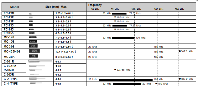
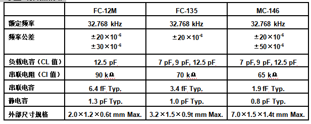
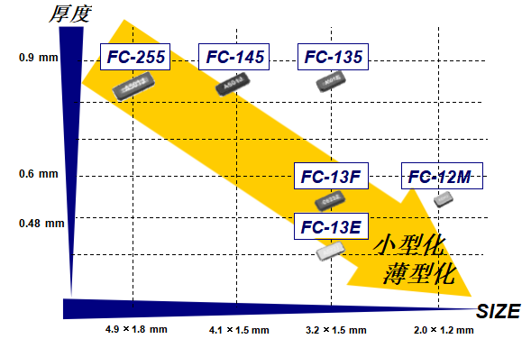
The lineup of Epson Toyocom's kHz frequency band tuning fork crystal units is as follows. From cylindrical to SMD models that can be automatically installed, the variety is abundant and can be applied to various purposes. Especially for the small main models MC-146 and FC-135, they are world standard sizes. And also in the
In March 2007, the ultra small, high-precision, low CI value, and low sensitivity FC-12M was launched into the market to meet the increasingly strong demand for miniaturization.
Overview of kHz frequency band tuning fork crystal units
Overview of Small Product Specifications
The trend of miniaturization in the FC series
4-2. 32.768 kHz oscillator
(1) 32.768 kHz crystal oscillator product lineup
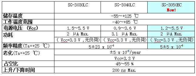
In addition to preparing a lineup of 32.768 kHz tuning fork crystal units for you, Epson Toyocom also commercializes 32.768 kHz crystal oscillators, which can be used for various purposes just like tuning fork crystal oscillators. So far, especially the small main model: SG-3030LC has made contributions to the development of products for many customers.
On top of this, our company has also developed the world's smallest 32.768 kHz crystal oscillator: SG-3050BC, which has superior performance compared to our original products.
Overview of 32.768 kHz crystal oscillators

Overview of specifications for 32.768 kHz crystal oscillator
The trend of miniaturization of 32.768 kHz crystal oscillators
About Epson Toyocom
Epson Toyocom Company was established in October 2005 by the merger of the Crystal division of Seiko Epson Co., Ltd. and the division of Toyo Communications Co., Ltd.
For crystal based "timing components", "sensing components", and "optical components", the "3D strategy" is based on the concept of "horizontal expansion" of each of these three components and "vertical expansion" of combining the three components. From the civilian field of mobile phone terminals to the industrial fields of communication infrastructure, vehicle, etc., we provide products to our customers worldwide and aspire to become a leading company in the crystal component industry.
Our company's "timing components" are crystal quartz products with high precision and stability, and are used as reference signal sources for various instruments and equipment. Tuning fork vibration in the KHz frequency band; AT type crystals that utilize thickness vibration below approximately 100MHz; In the hundreds of MHz frequency band, there are High Frequency Fundamental (HFF) and Surface Acoustic Wave (SAW) modes that utilize AT vibration technology, providing customers with various products in the kHz to 2.5GHz frequency bands.
Epson Toyocom website: http://www.epsontoyocom.co.jp/cn/


